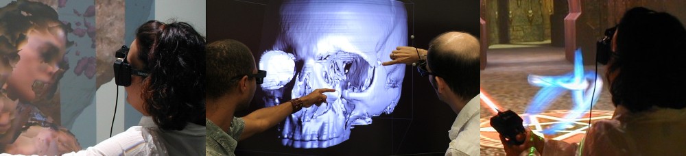
With the first commercial version of the Oculus Rift (Rift CV1) now trickling out of warehouses, and Rift DK2, HTC Vive DK1, and Vive Pre already being in developers’ hands, it’s time for a more detailed comparison between these head-mounted displays (HMDs). In this article, I will look at these HMDs’ lenses and optics in the most objective way I can, using a calibrated fish-eye camera (see Figures 1, 2, and 3).
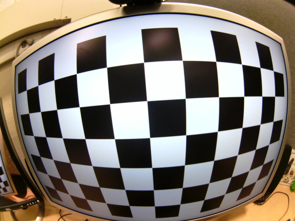
Figure 1: Picture from a fisheye camera, showing a checkerboard calibration target displayed on a 30″ LCD monitor.
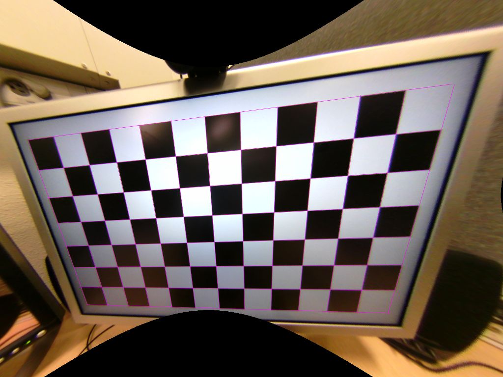
Figure 2: Same picture as Figure 1, after rectification. The purple lines were drawn into the picture by hand to show the picture’s linearity after rectification.
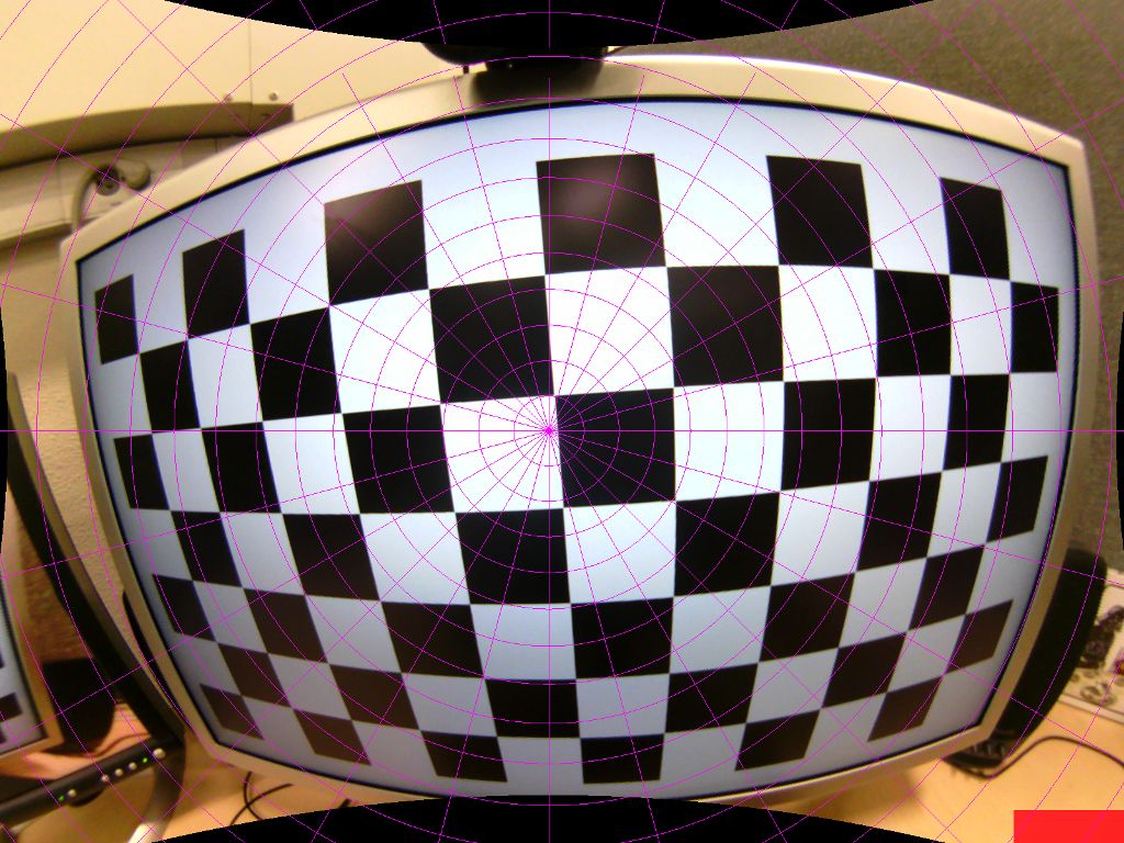
Figure 3: Rectified picture from Figure 2, re-projected into stereographic projection to simplify measuring angles. Concentric purple circles indicate 5-degree increments away from the projection center point.
Using such a camera, I can take pictures of exactly what a user would see inside the HMD, and at the same time measure sizes and angles directly and accurately. The basic method is to display a set of test images directly on the HMD’s screen(s) (without applying lens distortion or chromatic aberration correction, as 3D software would), and to take pictures of those test images from a set of positions relative to the HMD’s lenses, to account for users with different inter-pupillary distances and/or eye-lens distances (see Figures 4 and 5). In this first experiment, I kept the camera centered in front of its lens and only varied lens-camera distance. This is appropriate, given that the three main currently-availble HMDs (Rift CV1, Vive DK1, and Vive Pre) have physical IPD adjusters, meaning most users will be able to center the lenses with respect to their eyes.
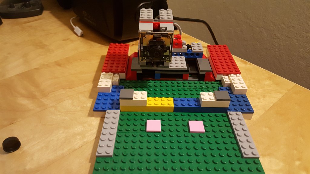
Figure 4: Adjustable fisheye camera rig.
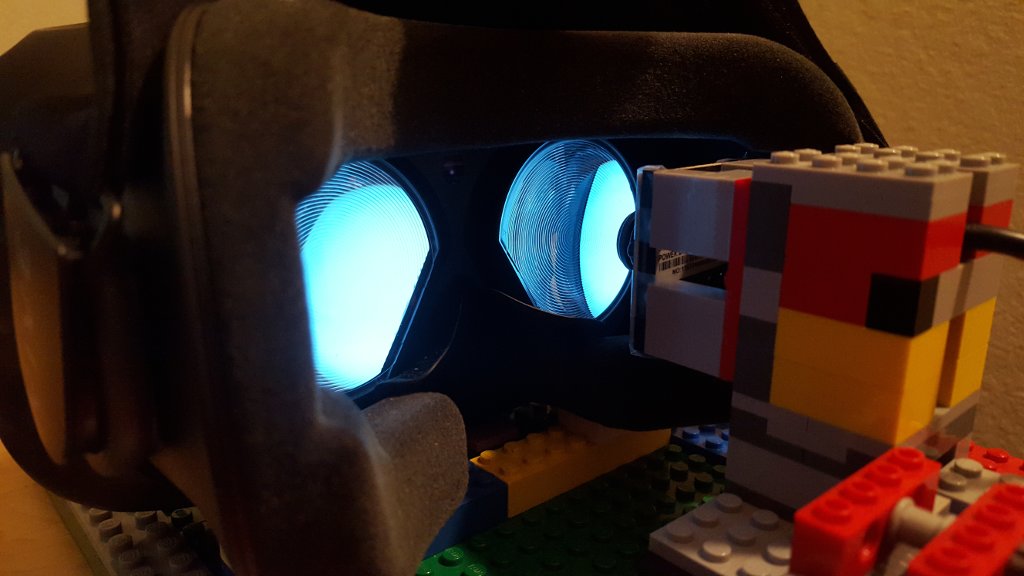
Figure 5: Adjustable fisheye camera rig, with HTC Vive Pre in place and showing test image.
Unfortunately, I was not able to run the full set of tests on the Oculus Rift CV1. Unlike the other HMDs, it does not work as a straight display when plugged into a computer; it requires Oculus’ run-time software to be installed, which prevents displaying arbitrary non-distortion corrected images on its screens. I was only able to run the field-of-view tests, using pictures taken inside several Oculus VR applications (home screen, Dream Deck, Lucky’s Tail).
Lens Distortion and Chromatic Aberration Test
The first test looks at the distortion and chromatic aberration (color fringes) caused by an HMD’s lenses, mostly to get an idea what the different lenses’ properties are. The test displays a simple grid of white lines on a black background. Note that the following images show raw distortion: this is not what the display from a VR application would look like.
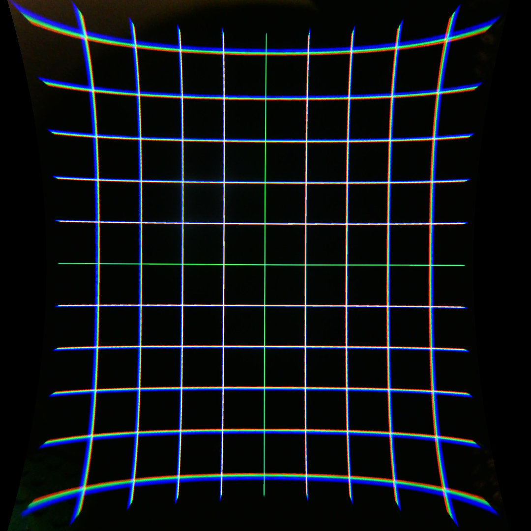
Figure 6: Lens distortion and chromatic aberration test, Oculus Rift DK2. Center lines are green on purpose.

Figure 7: Lens distortion and chromatic aberration test, HTC Vive DK1.
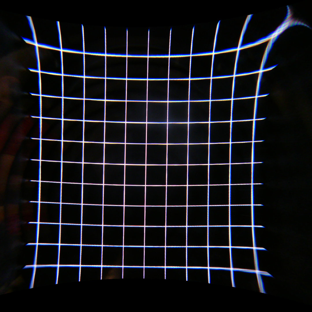
Figure 8: Lens distortion and chromatic aberration test, HTC Vive Pre.
Note that the HTC Vive DK1 and Pre have somewhat less geometric distortion and chromatic aberration across the image than Oculus Rift DK2, but show some Fresnel fringing towards the perimeter. Also note that the Vive DK1 and Pre images look very similar, indicating that they have very similar or identical lens/screen systems. In the following, I will only show pictures from both Vive DK1 and Vive Pre in cases where there are significant differences.
Glare Test
One thing that I noticed immediately when I put on the Oculus Rift CV1 for the first time was a surprising amount of glare, caused by the ridges of its Fresnel lenses. I had not noticed glare this strong when using HTC Vive DK1 and Pre before, which both use Fresnel lenses as well. To put it to the test, I displayed a high-contrast image of white text on black background, because glare in the Rift CV1 was most noticeable in the opening screens of EVE:Valkyrie, which feature white text on black. Unfortunately, I was not able to run this test on Rift CV1 (see above), but here are the results from Rift DK2 and Vive DK1/Pre:
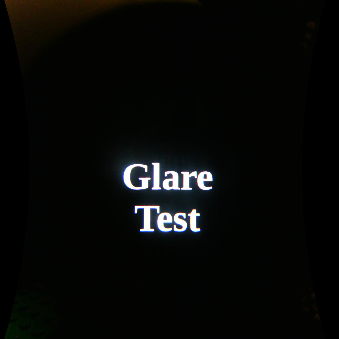
Figure 9: Glare test, Oculus Rift DK2.
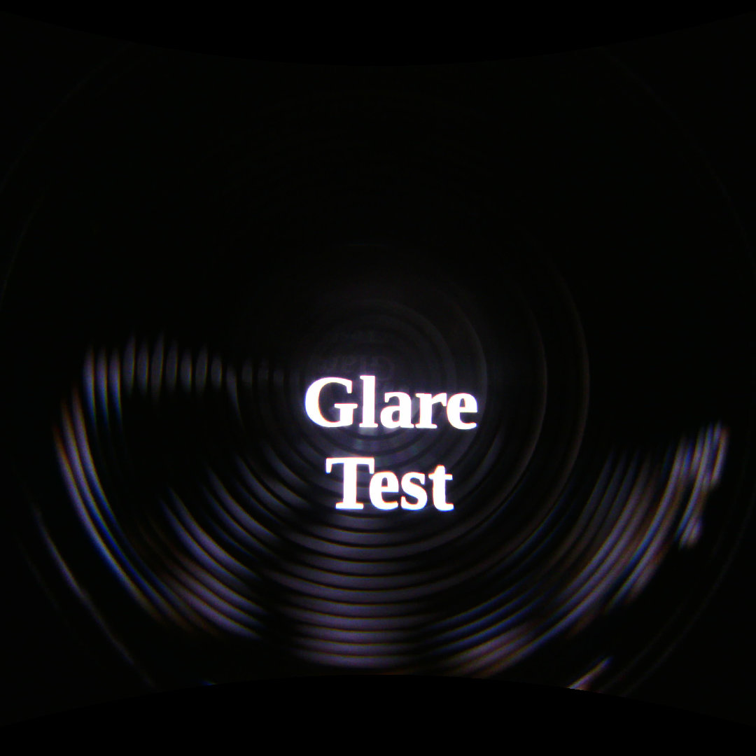
Figure 10: Glare test, HTC Vive DK1.
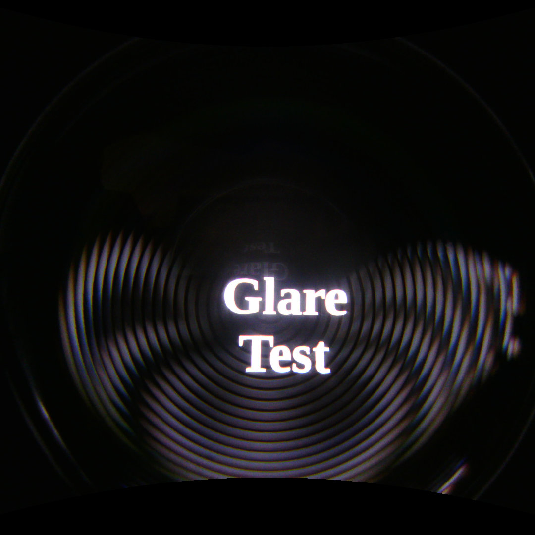
Figure 11: Glare test, HTC Vive Pre.
Note how the Oculus Rift DK2 does not exhibit glare due to its simple lenses, and that the glare effects in HTC Vive DK1/Pre show the relatively wide Fresnel ridges of their respective lenses. The slightly more pronounced glare in Vive Pre might be due to its brighter screen.
The effect in the Oculus Rift CV1 looked different, due to the Rift’s narrow Fresnel ridges. Subjectively, instead of distinct concentric circles, I saw crepuscular rays of the shape shown in Figure 12; not quite as strong, but distinctly noticeable and somewhat distracting. Unfortunately, I was not able to measure this effect objectively (see above).

Figure 12: Example of crepuscular rays (“god rays”), showing the shape — but not intensity — of Fresnel glare effects in Oculus Rift CV1. This picture is merely an illustration, not a real photograph taken in Oculus Rift CV1.
Field of View
The most important question for me — and the only one that really requires a rectified camera — was the size of the headsets’ fields-of-view. Field of view (FoV) is an important contributing factor to immersion and the effect of presence. However, unlike the effects described above, FoV — while being an objective measurement — is different for each viewer, as it depends on the relative position of the viewer’s eyes with respect to the HMD’s lenses (most importantly, lens-eye distance or eye relief), which in turn depends on a viewer’s head size and face shape, and how the headset is worn.
The way to address this issue is to measure FoV for a number of different lens-camera distances, in the following experiments 0mm (camera touches lens), 5mm, 10mm, 15mm, 20mm, and 25mm, and to additionally measure the lens-camera distance that maximizes FoV, and maximum FoV at that distance. These measurements allow a comparison between different HMDs, and would make it possible to estimate per-viewer effective FoV a-priori by measuring a person’s head shape.
I took these measurements by displaying a test pattern using the HMDs’ entire screens (960×1080 pixels per eye for Rift DK2, 1080×1200 pixels per eye for Vive DK1 and Pre). Another potential limiting factor for FoV is the VR rendering engine; for several reasons, an engine might only render to a smaller region of the screen, in turn reducing FoV. To test this, I also took pictures of VR applications running in Oculus Rift DK2 and HTC Vive DK1/Pre. For Oculus Rift CV1, this was the only way I could measure FoV (see above).
All following pictures, unless otherwise noted, are shown in stereographic projection (see Figure 3), to simplify angle measurement.
Oculus Rift DK2
Figures 13-18 show a test pattern in the Rift DK2, on the right eye, using lens-camera distances of 0mm, 5mm, 10mm, 15mm, 20mm, and 25mm:
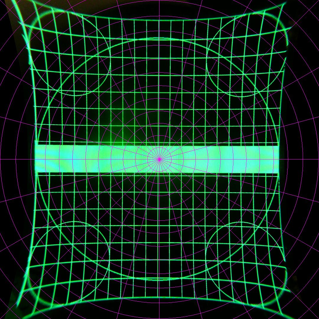
Figure 13: Test pattern in Oculus Rift DK2 at 0mm lens-camera distance. FoV is screen-limited.
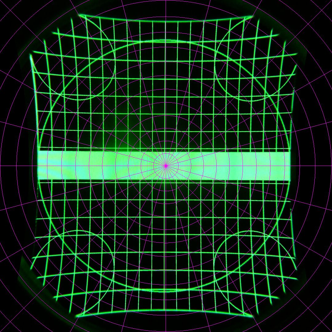
Figure 14: Test pattern in Oculus Rift DK2 at 5mm lens-camera distance.

Figure 15: Test pattern in Oculus Rift DK2 at 10mm lens-camera distance. Vertical FoV is now lens-limited.

Figure 16: Test pattern in Oculus Rift DK2 at 15mm lens-camera distance. Both horizontal and vertical FoV are now lens-limited.
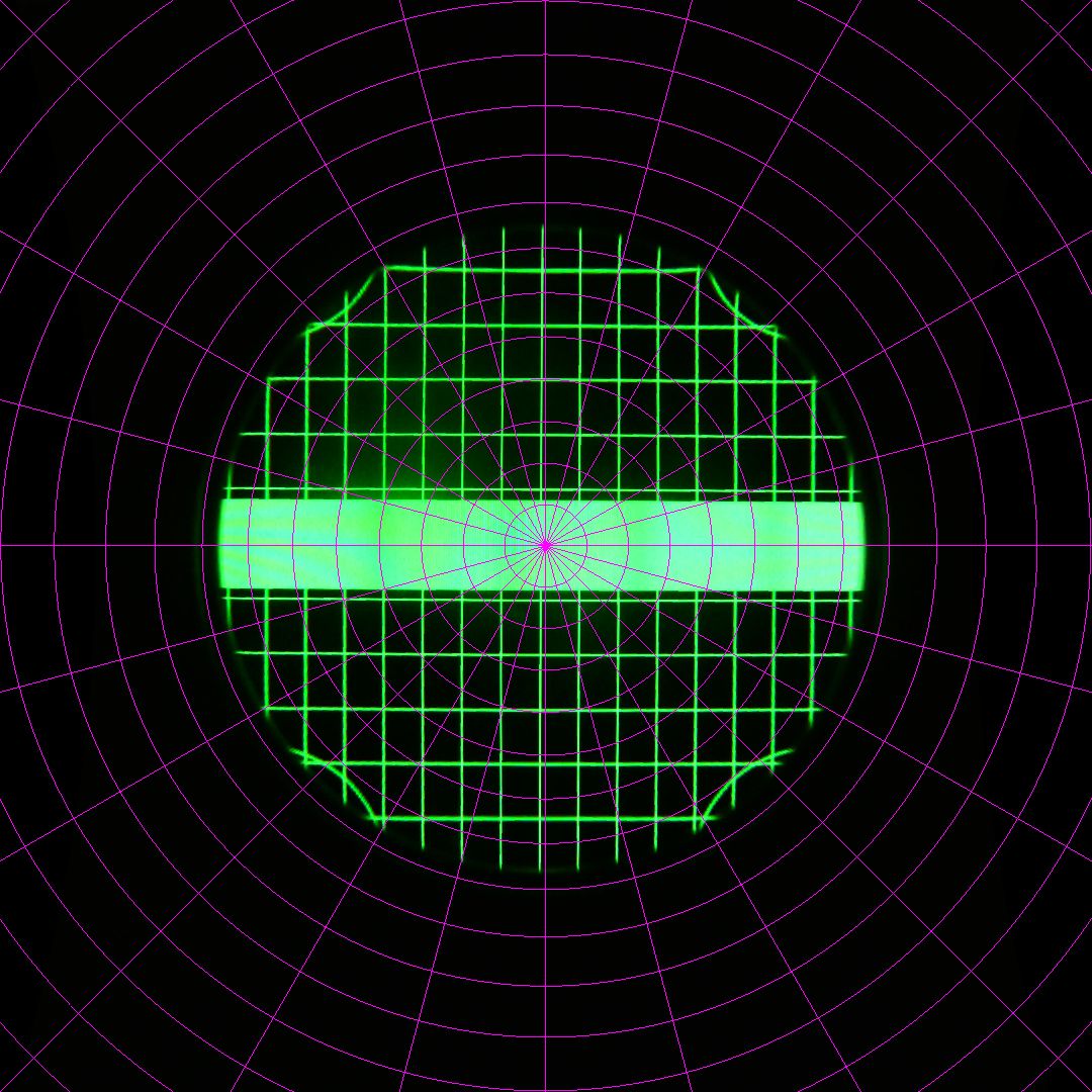
Figure 17: Test pattern in Oculus Rift DK2 at 20mm lens-camera distance.
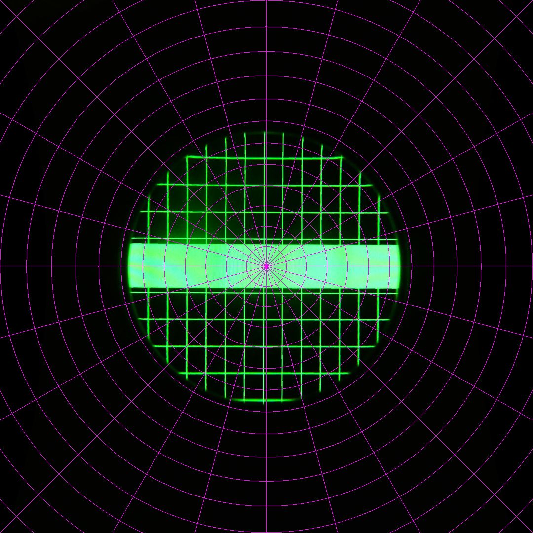
Figure 18: Test pattern in Oculus Rift DK2 at 25mm lens-camera distance.
Measuring horizontal and vertical FoV at the narrowest points of the bowties, we get:
| Lens-camera distance | 0mm | 5mm | 10mm | 15mm | 20mm | 25mm |
|---|---|---|---|---|---|---|
| Left Horizontal FoV | 49° | 48° | 47° | 45° | 38° | 34° |
| Right Horizontal FoV | 47° | 47° | 46° | 44° | 37° | 33° |
| Total Horizontal FoV | 96° | 95° | 93° | 89° | 75° | 67° |
| Vertical FoV | 107° | 106° | 104° | 99° | 76° | 66° |
The Rift DK2’s FoV is maximal at 0mm lens-camera distance, i.e., when the user’s eyeball touches the lens. This is generally not achievable, and the minimum eye relief configurable in the SDK is 8mm, with an effective binocular FoV of 94° x 105°. Figure 19 shows a picture of the SDK test scene, configured for minimum eye relief, and taken at 8mm lens-eye distance. This figure is in rectilinear projection to show the straight left and right edges of the view frustum (and the lens-limited circular top and bottom edges), and the quality of lens distortion correction (note the straightness of straight lines):
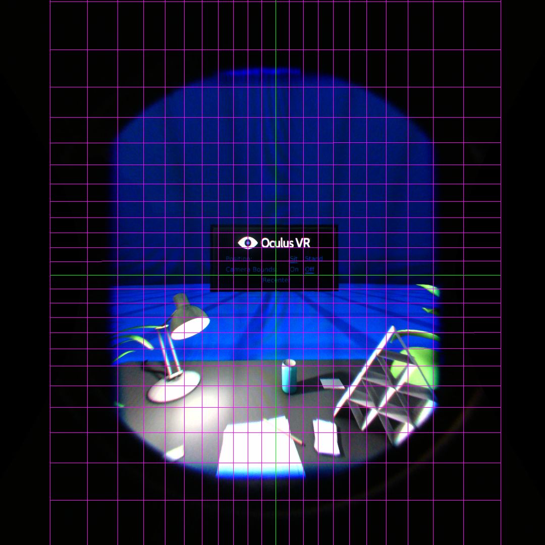
Figure 19: Picture of Rift DK2 test scene configured for minimum eye relief, at 8mm lens-camera distance. The picture is in rectilinear projection, with 5 degrees distance between horizontal and vertical purple lines, respectively. Horizontal and vertical FoV closely match the table above.
The difference between left and right FoV angles allows calculating the amount of overlap between the left and right views, and therefore the total binocular FoV. Taking the above measurements at face value, the right-eye view is slightly skewed to the left, leading to more than 100% stereo overlap, and a total binocular FoV (assuming that the left/right views are mirror images of each other) ranging from 98° (at 0mm distance) to 68° (at 25mm distance). Left/right FoV offset is difficult to measure accurately, but in the Rift DK2’s case, we can use the known internal HMD geometry to double-check the results. The DK2’s screen is 125.76mm wide, and the lens center distance is 63.5mm. This means the left and right lenses are slightly to the left and right of the centers of their screen halves, respectively, which skews the left/right view frusta towards the center. Plugging in the numbers yields a stereo overlap of 101%, which is consistent with the measured values (and might explain the slightly “blinkered” feeling when using a Rift DK2).
HTC Vive DK1/Pre
Figures 20-25 show a test pattern in the Vive DK1, on the right eye, using lens-camera distances of 0mm, 5mm, 10mm, 15mm, 20mm, and 25mm. Unfortunately, the Vive’s FoV is slightly larger than my camera’s vertical FoV, which means I had to take two sets of pictures, one with the camera rotated by 90°, and measure horizontal and vertical FoV separately. I am only showing the pictures measuring horizontal FoV; please take my word for the vertical FoV measurements listed after the pictures. Pictures from the Vive Pre are basically identical, and omitted for brevity:
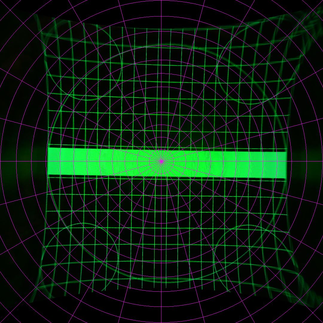
Figure 20: Test pattern in HTC Vive DK1 at 0mm lens-camera distance. FoV is screen-limited (test pattern is cut off at bottom due to fisheye camera’s limited vertical FoV).
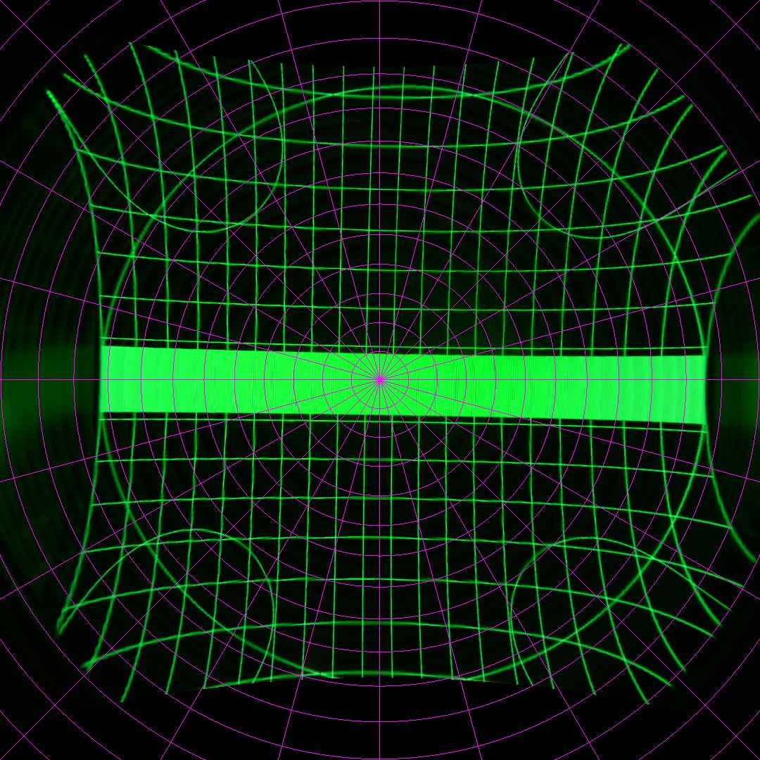
Figure 21: Test pattern in HTC Vive DK1 at 5mm lens-camera distance.
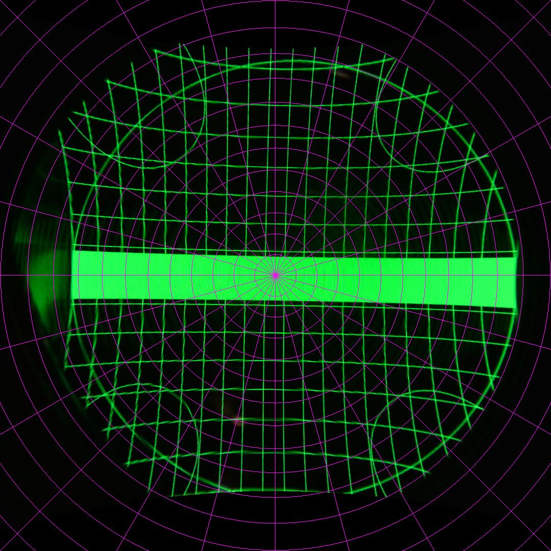
Figure 22: Test pattern in HTC Vive DK1 at 10mm lens-camera distance.
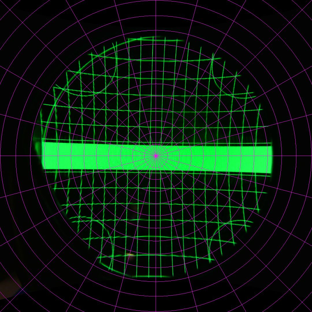
Figure 23: Test pattern in HTC Vive DK1 at 15mm lens-camera distance. Both horizontal and vertical FoV are now lens-limited.
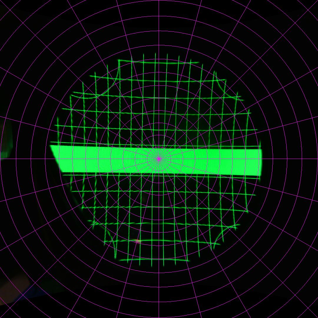
Figure 24: Test pattern in HTC Vive DK1 at 20mm lens-camera distance.
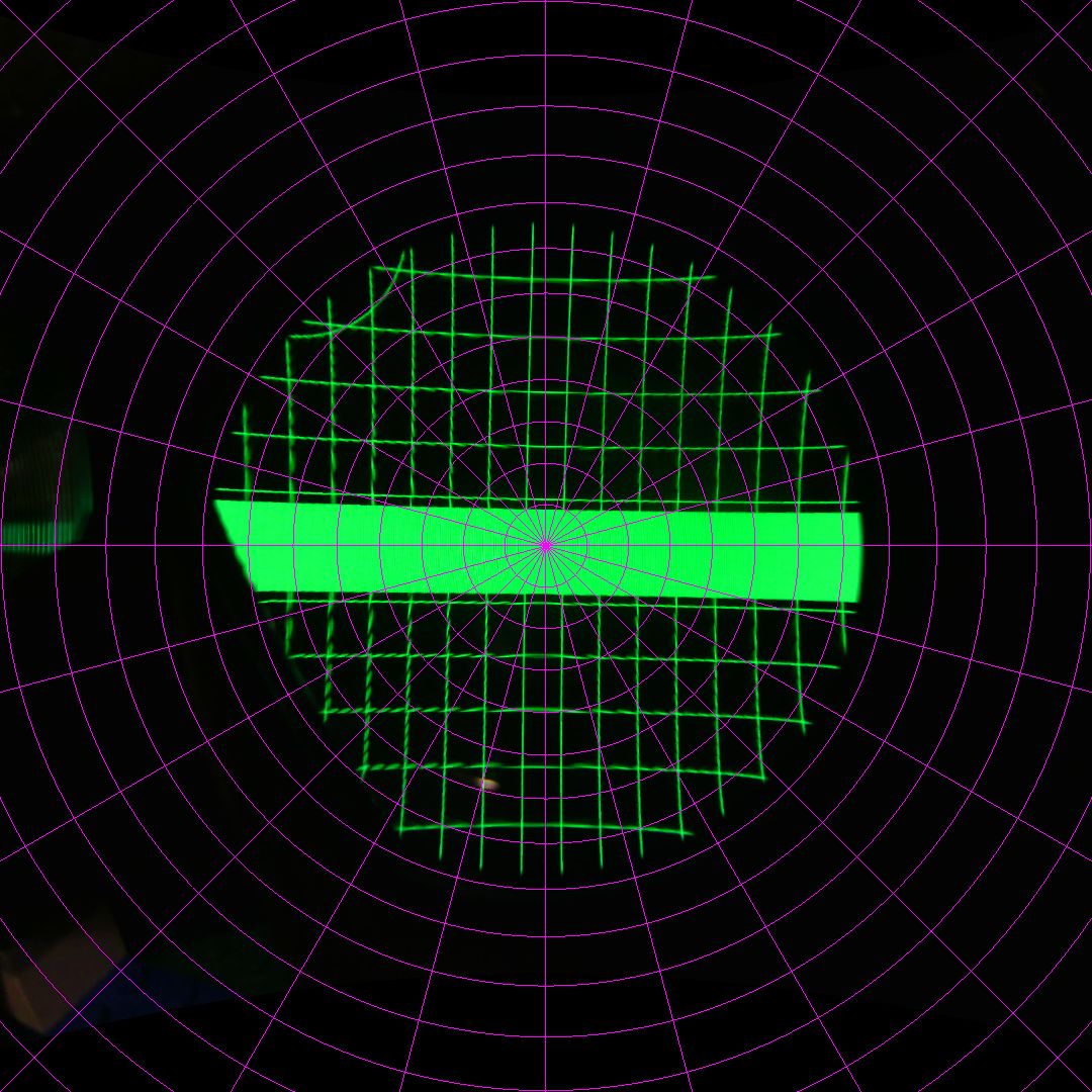
Figure 25: Test pattern in HTC Vive DK1 at 25mm lens-camera distance.
Measuring horizontal and vertical FoV at the narrowest points of the bowties, we get:
| Lens-camera distance | 0mm | 5mm | 10mm | 15mm | 20mm | 25mm |
|---|---|---|---|---|---|---|
| Left Horizontal FoV | 44° | 46° | 46° | 46° | 44° | 39° |
| Right Horizontal FoV | 48° | 53° | 54° | 47° | 41° | 37° |
| Total Horizontal FoV | 92° | 99° | 100° | 93° | 85° | 76° |
| Vertical FoV | 102° | 112° | 113° | 99° | 88° | 77° |
Unlike the Oculus Rift DK2, HTC Vive DK1/Pre reach their maximal fields of view at some distance from the lens, specifically at 8mm eye relief, which is practically achievable. Also unlike Rift DK2, the Vive DK1/Pre’s view frusta are skewed outwards, sacrificing stereo overlap for increased binocular FoV. At the ideal eye relief of 8mm, and again assuming that the frusta are mirror images, total binocular FoV is 110° x 113° (not included in above table). To reiterate, measuring FoV offset accurately is rather hard, and the resulting binocular FoV estimates, unlike monocular FoV measurements, are to be taken with a grain of salt.
Figures 26 and 27 show pictures of the SteamVR home screen at 8mm lens-camera distance, again in rectilinear projection. Figure 26 was taken with the camera in horizontal position, cutting off the top and bottom of the Vive’s FoV, and Figure 27 was taken with the camera in vertical position, cutting off left and right:
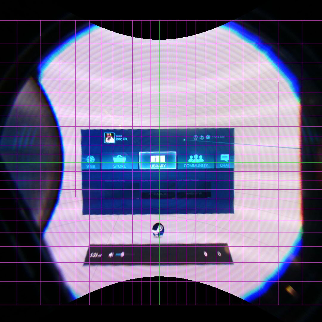
Figure 26: SteamVR home screen in Vive DK1 at 8mm lens-camera distance, in rectilinear projection. Top and bottom edges are cut off by fisheye camera’s FoV.
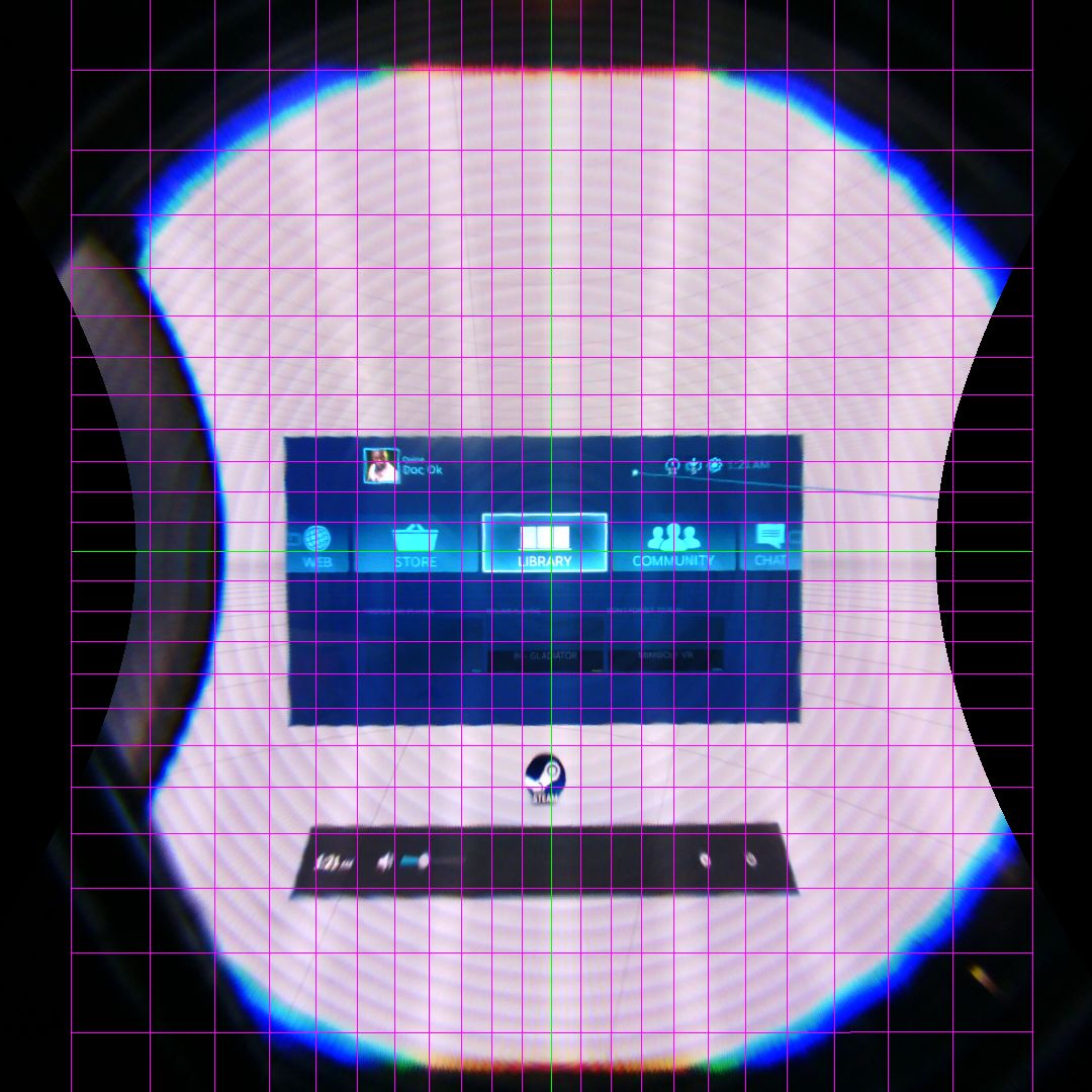
Figure 27: SteamVR home screen in Vive DK1 at 8mm lens-camera distance, in rectilinear projection. Right edge is cut off by fish eye camera’s FoV.
Oculus Rift CV1
As I mentioned above, the Rift CV1 did not allow me to display test images. I had to limit my experiments to measuring FoV using images rendered by the VR engine. Figures 28-33 show the in-game setup screen in the Rift CV1, on the right eye, using lens-camera distances of 0mm, 5mm, 10mm, 15mm, 20mm, and 25mm.
These images are to be taken with a grain of salt. I did my best to center the camera with respect to the right lens and aim it at the display’s center of projection, and the total monocular FoV will be quite good, but due to my inability to display a targeting image, I cannot guarantee that the left/right horizontal FoV measurements, and therefore the total binocular FoV estimates, will be as accurate as those for the other headsets. In Oculus lingo, they will be “in the ballpark.”
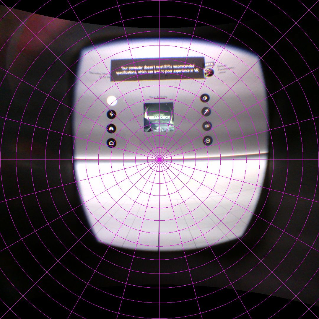
Figure 28: In-game setup screen in Oculus Rift CV1 at 0mm lens-camera distance.
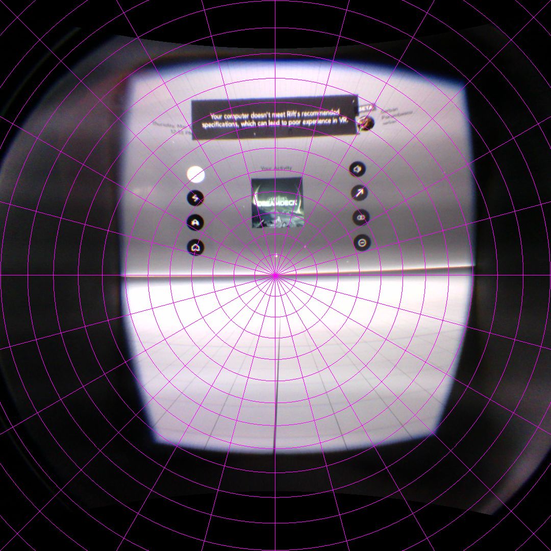
Figure 29: In-game setup screen in Oculus Rift CV1 at 5mm lens-camera distance.
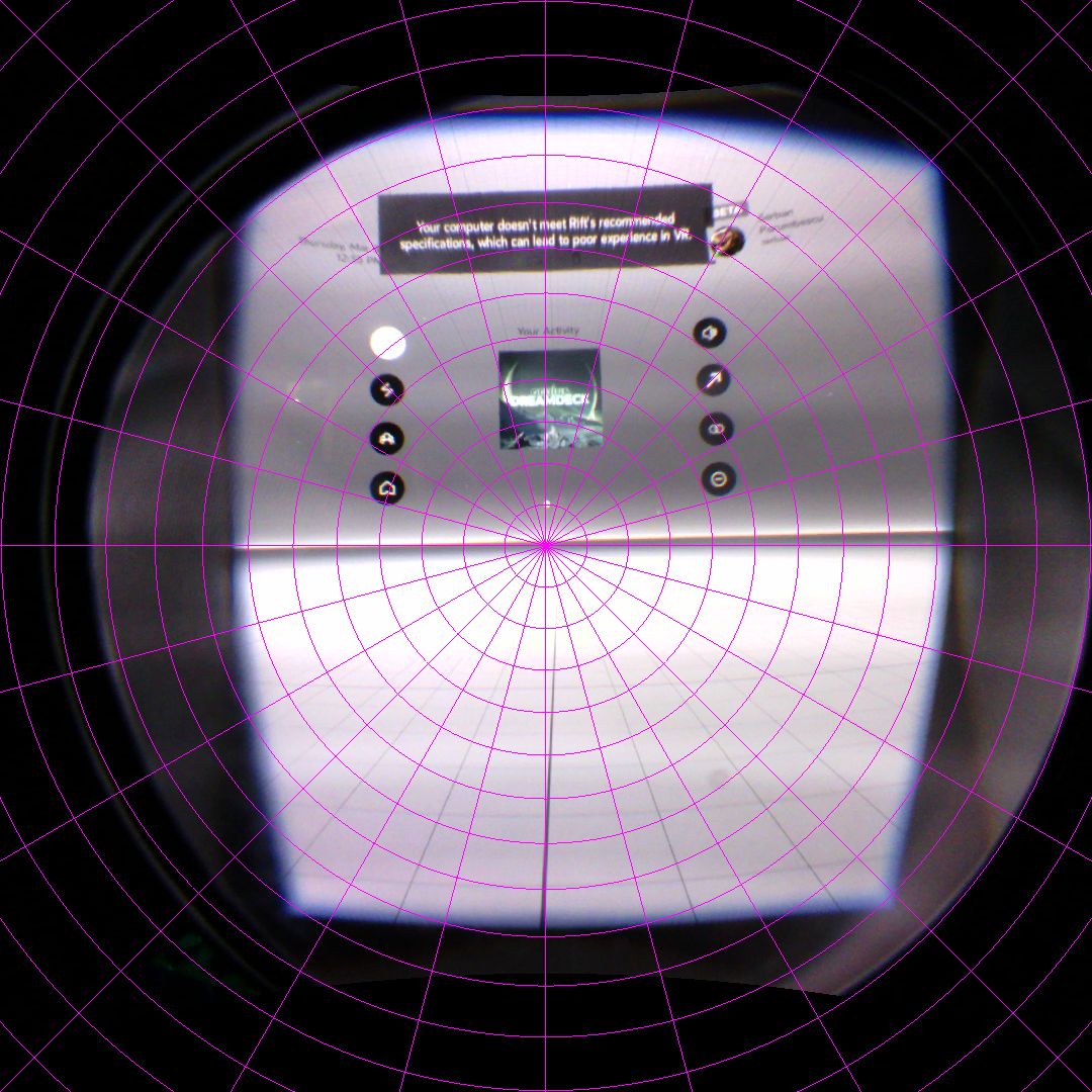
Figure 30: In-game setup screen in Oculus Rift CV1 at 10mm lens-camera distance.
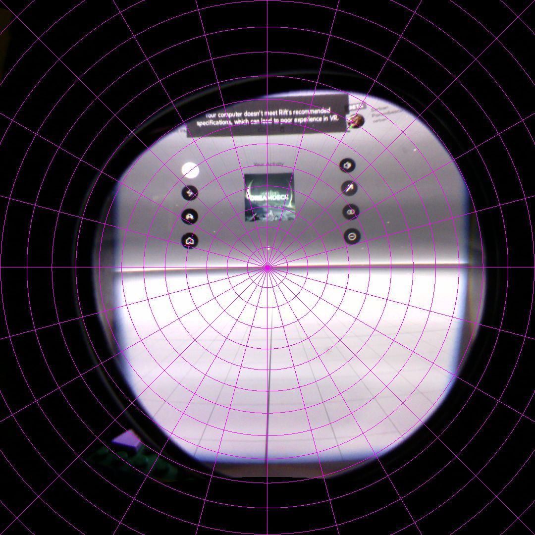
Figure 31: In-game setup screen in Oculus Rift CV1 at 15mm lens-camera distance.
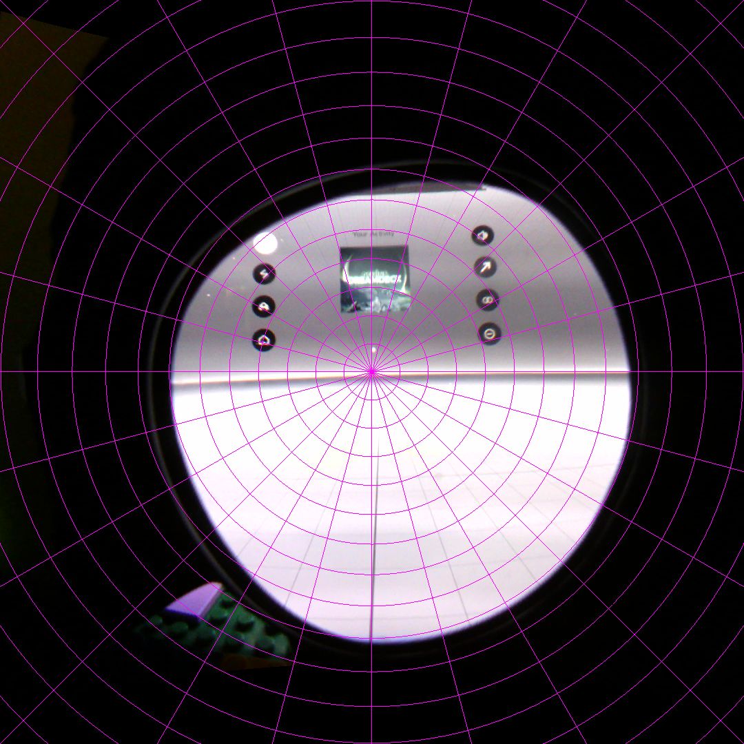
Figure 32: In-game setup screen in Oculus Rift CV1 at 20mm lens-camera distance.
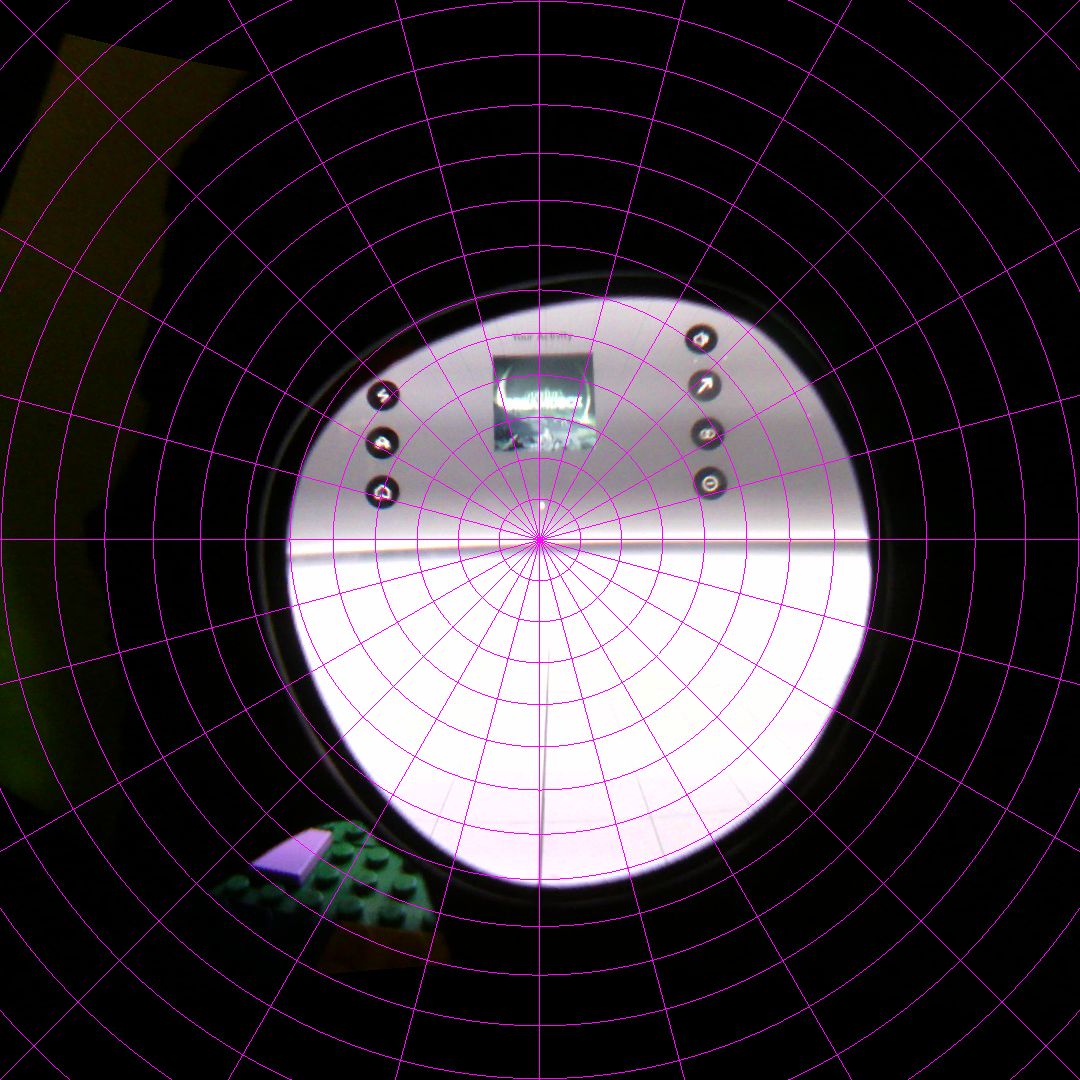
Figure 33: In-game setup screen in Oculus Rift CV1 at 25mm lens-camera distance.
Measuring horizontal and vertical FoV at the vertical and horizontal centers, respectively, we get:
| Lens-camera distance | 0mm | 5mm | 10mm | 15mm | 20mm | 25mm |
|---|---|---|---|---|---|---|
| Left Horizontal FoV | 35° | 36° | 37° | 37° | 35° | 30° |
| Right Horizontal FoV | 43° | 45° | 47° | 47° | 44° | 39° |
| Total Horizontal FoV | 78° | 81° | 84° | 84° | 79° | 69° |
| Vertical FoV | 84° | 89° | 93° | 86° | 78° | 69° |
As in Vive DK1/Pre, the maximal FoV is achieved at some distance from the lens, in this case 12mm. Taking the left/right FoV value differences as accurate, the total binocular FoV at that lens-camera distance is 94° x 93°.
Figure 34 shows another picture, this one from Lucky’s Tail (or is it Luckey’s Tale?), again in rectilinear projection:

Figure 34: Shot from Lucky’s Tail in Oculus Rift CV1 at 12mm lens-camera distance.
Comparing Field of View
As is evident from the pictures I posted, reducing an HMD’s FoV to two numbers (horizontal angle times vertical angle) does not do it justice entirely. For example, the Rift CV1’s FoV is rectangular at 12mm lens-camera distance (see Figure 34), whereas the Rift DK2’s FoV is capsule-shaped (circular at top and bottom and straight on the sides, see Figure 19). Vive’s FoV is more circular, with a strange bite missing on the inner side (see Figures 26 and 27).
The best way to compare fields of view is to use the pictures themselves, which are all using the same projection (unless otherwise noted), and are shown at the same scale. To compare two specific setups (HMD with lens-camera distance), load the two corresponding pictures into your favorite image editing software, and overlay them. For example, Figure 35 shows the FoV of Rift DK2 overlaid onto the FoV of Rift CV1, both at 10mm, close to their optimal lens-camera distances.
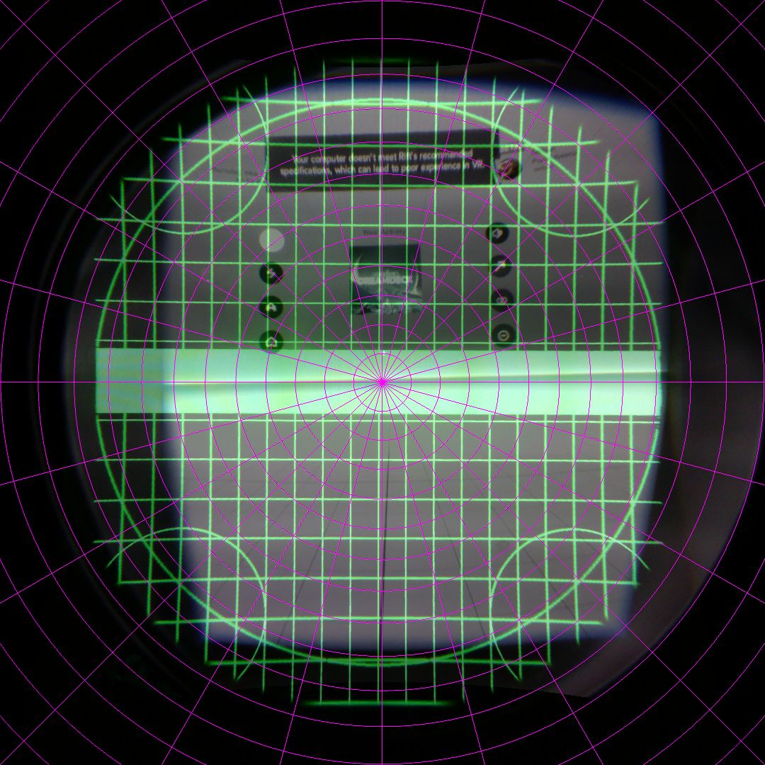
Figure 35: FoV of Oculus Rift DK2 at 10mm overlaid onto FoV of Oculus Rift CV1 at 10mm.
Figure 36 shows the binocular FoV of Oculus Rift CV1 at 10mm, and finally, Figure 37 shows the binocular fields of view of Oculus Rift DK2 and CV1, both at 10mm, overlaid onto each other. It can be seen that the horizontal FoV matches almost exactly, but the vertical FoV is different.
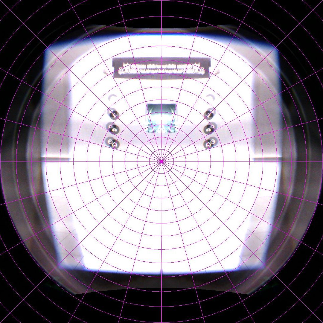
Figure 36: Binocular FoV of Oculus Rift CV1 at 10mm lens-camera distance, simulated by overlaying the right-eye FoV with a mirror image of itself.
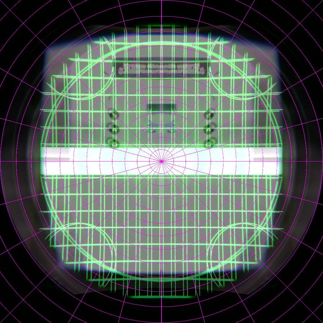
Figure 37: (Simulated) binocular FoVs of Oculus Rift DK2 at 10mm and Oculus Rift CV1 at 10mm overlaid onto each other.

Did you account for overlap? It looks like youve just measured each lens and doubled it, but people seem to say the CV1 lenses are offset and not 100% overlap like that?
Yes, I accounted for overlap. Carefully read the paragraphs after each FoV table.
Hi,
I see that you have accounted for the overlap, but if the two lenses are seeing the same image (100% overlap), isn’t the Binocular horizontal FOV the same as the monocular FOV? Which would mean that Rift Horizontal FOV is more like 37 or 47 (depending on the image overlap on each eye), but you couldn’t really add the two to get a ‘total’ FOV.
I am not an expert, so I may have misunderstood the write-up after the FOV tables, in which case, I would love to get some more references around this.
To be able to calculate stereo overlap and binocular FoV, I measured all headsets’ horizontal half-FoVs from the center line to the left, and from the center line to the right. If you add up those two values, you get the total (monocular) horizontal FoV of each lens/screen. In the CV1’s case, at 10mm eye relief, that’s 37°+47°=84°, as printed in the table. To get the total binocular horizontal FoV, you need to calculate the opening angle of the union of the two lenses’ view frusta, which is twice the larger of the two half-FoVs. Again in the CV1’s case, it’s 47°+47°=94°.
Thanks for the hard work!
Is it possible for you to display the test images you require using Virtual Desktop?
I suppose the movement of the headset is probably just as big of a problem as getting the image on the screen.
This is a great review, thank you for putting this up. I was tempted to oculus, but seeing @10mm vive 100°/133° VS cv1 84°/93° makes me think again. It’s a huge difference on paper, is this difference noticeable by that much if you do A-B test?
It’s subjective, but if you ask me, both are big enough (and well-aligned enough) that the difference is not immediately obvious.
You mean 100/113 for the vive
yep 100/113, my mistake
Could you detail a bit more the methodology to get the “glare” images? Did you histogram-stretch them to see the banding or are they straight from the camera? Also, does the camera have auto-exposure on?
Those are raw images color-wise, with auto-exposure on to better simulate how a viewer would see them. Given unknown auto-exposure algorithms and measurement zones, and unknown amounts of gamma correction in the camera, these are hardly quantitative, but they capture pretty well what such a high-contrast scene looks like via naked eye.
Beautiful work. If you want to deepen the glare study, you might consider taking a series of exposures of the same shot, to create a high dynamic range image. In particular, be sure to include exposures low enough that the white central subject does not saturate the camera sensor. Then you might be able to roughly quantify the relative intensity of the glare.
Really great article. Thanks for taking the time to do this.
I’ve personally noticed that the glare is especially obvious in each headset when bright elements are located toward the periphery. These Vive glare shots just seem to highlight the fresnel ridges, but I’ve found the Vive also has a (milder) “crepuscular” effect with peripheral bright spots as well…
Camera to lens distance is important, but very short distances are impractical because of eye relief. The eyelashes would hit the lens or general discomfort would result. Typical eyeglasses are about 12mm from the eye, so probably not practical to assume anything than 10 mm.
Otherwise – excellent work! Do you plan to open-source it?
I included the short-end eye relief measurements to counter a common misconception (for Vive / CV1), namely that you have to mash your eyes as closely against the lenses as possible to get maximum FoV. I don’t want people plucking their eyelashes, or scratching their corneas, only to end up with a smaller FoV in return.
Pingback: Oculus Rift Review: Fazit der US-Medien *Update: Sichtfeldweite*
Great work!
There may be a small error in FOV measurements.
Stereographic projection, concentric circles on the image do not represent same angles. y = 2*f*tan(theta/2).
For angle measurement, equidistant projection (i.e. f-theta) is typically used. y = f * theta. concentric circles in f-theta mapping represent same angle separation.
https://en.wikipedia.org/wiki/Fisheye_lens#Fisheye_lens
Check the pictures again. Concentric circles representing 5 degree increments are not equidistant.
OK, I see.
Why does re-projection into stereographic projection simplify measuring angles? I didn’t get that
It reduces the stretching of angles away from the center compared to rectilinear projection, which makes it easier to eyeball angles accurately without having to use special measurement tools, and most importantly — although I didn’t use that feature here — it is conformal, meaning it locally preserves angles.
How do those results compare to previous generation (pre-Rift) VR headsets?
For the Vive it looks like about 100 of the 320 squares are lost at 10mm. This would give roughly (2160 * 1600) * (200/320) = 1,620,000 effective pixels out of 2,592,000
I’d expect the CV1 to have higher pixel density too, the total area of the image in figure 35 shows the Vive’s (1/2 * 1,620,000) pixels for a single eye taking more area then CV1’s seemingly full (1/2 * 2,592,000) pixels
Pingback: VR-Brillen-Vergleich: Oculus Rift
Pingback: VR-Brillen-Vergleich: HTC Vive Pre mit Steam VR
Do we now have a single number metric for CV1 FOV?
E.g Vive is 110′ Playstation VR is 100′
Thanks
Pingback: HTC Vive Review: A Mesmerising VR Experience, if You Have the Space - Road to VR
With regards to the Vive’s optics, I think the strange cut-outs on the inside edge are designed to prevent the user from seeing the inside peripheral edge (screen edge / cups).
I have tried both the Rift CV1 and the Vive and on the Rift CV1 I can easly see dark vertical bands at about 20% and 80% across my view. What I think I am seeing is each eye’s view of the dark peripheral inside edge doubled up in my stereo view.
Of course different people will notice different kinds of optical floors to a greater or lesser degree.
When I tried the Vive, I didn’t notice these dark vertical bands, due to each eye’s view of the inside edge. If I really tried I could see the outside screen edge. When I saw the strange chunk missing from the inside edge of the Vives optics, I totally made sense to me. It prevents me from seeing the inside edges of the screen or the cups that separate the screen and lense.
Not meaning to pick on the Rift CV1, but I found the ‘God-rays’ to be just awful, especially in game with a dark environment. I only spent 20mins with the Vive, so I can’t comment further, only to say I have one on order.
Dumb question but, in order to achieve 12 mm distance for maximal fov in the vive, would my cornea need to be 12mm from the lense or retinas? I am using a ruler now and doing a facepad modification and was just curious as to where the camera in my eyes lie.
The distances I measured were HMD lens surface to camera lens surface, which roughly corresponds to HMD lens surface to cornea surface. To be more precise, the measurements should have been from HMD lens optical center to eye/camera optical center, which for the eye is a few mm behind the cornea, but that’s not what I did.
Could you provide a sentence or two elaboration on the issue related to displaying arbitrary images to Rift CV1? I assume you are referring to the fact that in the SDK, submitted frames are passed to the Compositor process, which does the distortion. As I understand it, developers do not (really) have access to the Compositor, making it difficult or not impossible to do low-level implementations in the SDK (v1.0.0+).
*or impossible
I actually heard the at Vive team is specifically creating negative overlap – so the eyes can “fill the blanks”. Does this make sense to anyone??
Cheers
Hi ,
In Figure-2, the image is a rectification image. How to get this rectification image? Which software did you use?
I try to use Photoshop for image rectification but the result is not good.
Thanks,
Tony Ho
Figure 2 is the result of correcting a raw image with lens distortion correction parameters I calculated using camera calibration software I wrote.
Hello Sir,
Thank you for your reply.
I have another question. In Figure-1, how long between camera and screen?
I supposed the correction parameters are changed in different distance. So the distance between camera and screen is important. How to decide it?
Hi,
I’m trying to write a free software driver for the CV1: https://github.com/ThibG/OpenHMD/tree/dev-oculus-cv1
It’s not really useful, but it should enable you to bring the screens on without the official driver, thus letting you put whatever you want on the screen, without the corrections applied by the SDK.
Hi, fantastic post! I keep coming back to it for reference. Like you, I need to do some tests by displaying my own images on a headset and making measurements; I just got a Vive since you were successful with the developer kits.
Unfortunately my windows pc doesn’t show the headset as a monitor. 🙁 My mac detects it but is unable to display anything.
Did you have to do anything special to have either of the Vive headsets show up?
Here’s hoping that the sdk allows developers to display “raw” images on the headset displays…
Thanks for any advice!
I’m not sure about Windows. Under Linux, the Vive shows up as a regular 2160×1200 display when I plug it in, and I can use it as a desktop or display showing anything I write into the frame buffer.
I haven’t looked at the Windows setup much, but there is a “direct mode” setting which hides the Vive’s display from Windows to make VR rendering more foolproof. That’s probably what you’re running into. I don’t know if there’s some toggle to turn it off completely, so that the Vive appears as a display again.
It was indeed the direct mode setting! (Which seems to do more than make things foolproof; it improves performance.)
Thanks very much!
That was impressive. May I have further information about the test, what kind of software/hardware you did during the test, so how could you precisely get the current image from HMD image?
Really pressure to hear back from you.
About the lens distortion test, for Figure 6, 7, and 8, you took pictures with fish-eye camera and then correct the camera distortion with the software, right?
is there any android app to measure FOV of a HMD device?
Do you mean an app running on the smartphone inside a Google Cardboard clone, or a separate app to use an Android phone and its camera to measure the FoV of some other HMD?
Methods of measuring an HMD’s FoV from inside VR are unreliable because they rely on the HMD having been configured properly in the first place. For example, if you set the FoV of some first-person shooter to 90°, that doesn’t mean your monitor’s FoV is 90° (it’s typically around 30°).
Hi,
Have anyone seen numbers for focal distances?
Would be interested in understanding feasibility of exhanging the fresnel lenses to non fresnel ones on my Vive, I have very little sympathy for the god rays.
I have seen that the PS VR HMD uses standard, and would not mind the additional weight.
Any advice?
The lens/screen system needs to be carefully calibrated for the VR illusion to work (see How VR Works: A Perceptual Point of View). If you remove the original lenses and put in your own, you are going to have a bad time, unless you also run your own calibration process, and override the calibration parameters that are stored in the headset’s firmware and communicated to OpenVR applications.
Compared to geometric lens distortion, chromatic aberration, and field-of-view mismatches, god rays are a minor nuisance.
To answer your question, the Vive’s and Rift CV1’s virtual screen distance is reportedly infinity; the Rift DK2’s virtual screen distance is at around 1.4 meters. If you’re asking about the lenses’ focal lengths, I don’t know them off-hand, but you could calculate them from the virtual screen distance and real screen distance.
Do you think to also test the psvr headset? Would be great to get this kind of review also for this. The review is very informative thank you very much.
If someone were to send me a PSVR headset, I’d gladly give it a thorough test…
Thank you for your good work.
Can you mention the distance between the camera lens to the image sensor?
Usually the cornea and the retina is 17mm, plus 8mm minimum distance of eye relief, so the minimum distance from the headset lens to the retina is 25mm.
In the summary FoV table, the distance 0mm, 5mm, 10mm and so on is from the camera lens to the headset lens. To know what FoV users get I think the distance from the camera lens and the image sensor need to be accounted.
Thanks for your very hard work.
One question:
How to do the figure 2 to figure 3 stereographic reprojection?
Is there any software to support that?
It’s a non-linear 2D transformation. Calculate the ray direction for each pixel in the rectified image based on measured camera parameters, then feed that ray into the stereographic projection equation to get the new pixel position. I’m doing it by texture-mapping the source image onto a distorted quad mesh with pre-computed texture coordinates.
Many thanks for your sharing!
I can get camera parameters but still confused how to do stereographic or rectlinear reprojection.
I search “stereographic” and “rectilinear” respectively in OpenCV online documentation(http://www.opencv.org.cn/opencvdoc/2.3.2/html/index.html) but there is no match.
So I wonder is there a ready-made method in OpenCV or any other open source to do stereographic and rectlinear reprojection?
I don’t know OpenCV, but the math behind these projections is simple.
“Adjustable fisheye camera rig”
Cool
Thanks for sharing this.
hi do you have more details about the fisheye camera, the module?
thanks very much.
No, it’s a no-name 5MP wide-angle cam I found on Amazon.
…
Never mind, found it.
Sorry for thread necromancy – but I just bought this camera too, for similar purposes 🙂
I know you mentioned you did your own camera calib and rectification, not OpenCV, but I’m wondering what kind of model you used, for which the simplest references I have are in the OpenCV docs…
Were you able to use a pinhole camera model with radial and tangential distortion terms as found here: http://docs.opencv.org/3.2.0/d9/d0c/group__calib3d.html#details ?
Or did you use an explicitly fisheye model, e.g. http://docs.opencv.org/3.2.0/db/d58/group__calib3d__fisheye.html#details ?
I’m using a modified version of the Brown-Conrady lens distortion correction equation with radial and tangential terms with inverse radius weighting, which — I think — is the same model used by OpenCV. I chose the inverse radius term after comparing it to the original method and seeing smaller RMS approximation residuals.
I didn’t have to use a fisheye model as the camera has less than 180° FoV across the diagonal. Rectifying to an intermediate pinhole model worked fine.
Nice article.
It would be also interesting to see a comparison to “passive HMDs”, i.e. just “smartphone holders”.
Also, a very important parameter is the screen resolution, as keeping the eye so close to the display means that pixels must be very small to be not distinguishable (see “visual acuity”), else you’ll see a “screen-door effect”.
A 720 lines phone offers a poor immersive experience, as pixels are celarly distinguishable, but I also noticed this “defect” in standalone HMDs (don’t remember which models).
I setup this interactive page to “play” with visual acuity, display size and viewing distances:
http://jumpjack.altervista.org/acuita/
Although it is designed for TV sets, it is also suitable for HMDs and smartphones: for example, for 8cm eye-display distance you’d need at least 2684 lines resolution if you use a 5″ display.
Pingback: NED: Gaps In Pixel Sizes | Karl Guttag on Technology
Pingback: Measuring the Effective Resolution of Head-mounted Displays | Doc-Ok.org
I saw the specs of the new windows mixed reality hmd, on the paper they are 95° of fov. I wish to ask you if in your opinion their fov will be bigger than the one in oculus rift CV1 or smaller. have you read anything about it? thanks
I haven’t seen those in person yet, and if a manufacturer cites a single number for FoV, my first assumption is that it’s a lie. As the results in this article show, things are more complicated than that.
I’d love to get my hands on some of those headsets to do real measurements.
Pingback: The Display Resolution of Head-mounted Displays, Revisited | Doc-Ok.org
Pingback: Valve Index Is $999: 1440x1600 LCDs, 120 Hz, Wider Field Of View
Pingback: Field of View and Resolution of the PlayStation VR Headset | Doc-Ok.org