Last weekend, we had yet another professional film crew visiting us to shoot video about our involvement in NASA’s still on-going Mars Science Laboratory (MSL, aka Curiosity rover) mission. This time, they were here to film parts of an upcoming 90-minute special about Mars exploration for the National Geographic TV channel. Like last time, the “star” of the show was Dawn Sumner, faculty in the UC Davis Department of Earth and Planetary Sciences, one of the founding members of KeckCAVES, and member of the MSL science team.
Unlike last time, we did not film in the KeckCAVES facility itself (due to the demise of our CAVE), but in the UC Davis ModLab. ModLab is part of an entirely different unit — UC Davis’s Digital Humanities initiative — but we are working closely with them on VR development, they have a nice VR environment consisting of two HTC Vive headsets and a large 4.2m x 2.4m screen with a ceiling-mounted ultra-short throw projector (see Figure 1), their VR hardware is running our VR software, and they were kind enough to let us use their space.
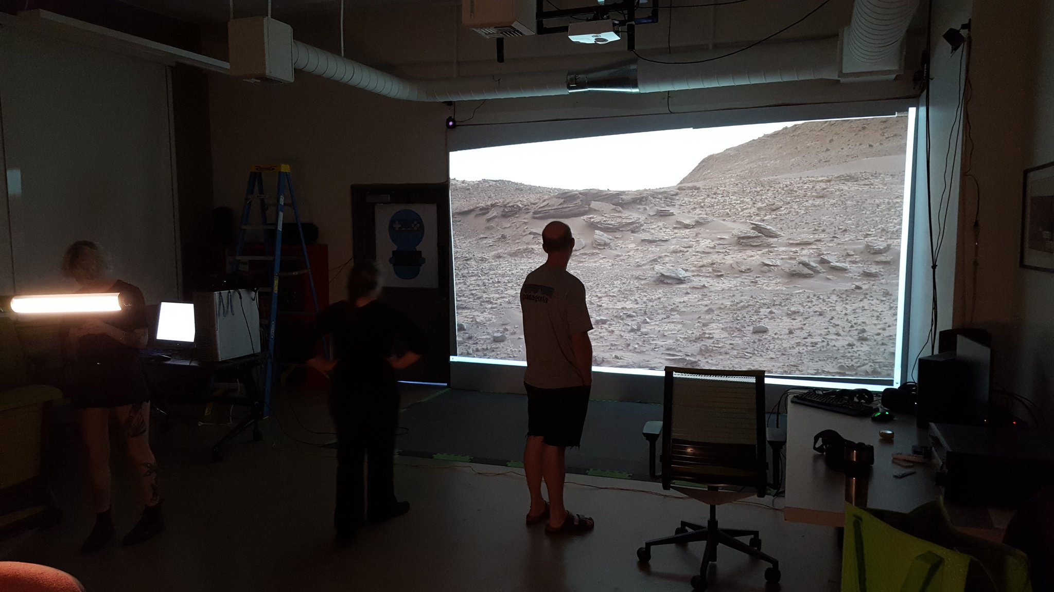
Figure 1: Preparation for filming in UC Davis’s ModLab, showing its 4.2m x 2.4m front-projected screen and ceiling-mounted ultra-short throw projector, and two Lighthouse base stations.
The fundamental idea here was to use several 3D models, created or reconstructed from real data sent back either by satellites orbiting Mars or by the Curiosity rover itself, as backdrops to let Dawn talk about the goals and results of the MSL mission, and her personal involvement in it. Figure 1 shows a backdrop in the real sense of the word, i.e., a 2D picture (a photo taken by Curiosity’s mast camera) with someone standing in front of it, but that was not the idea here (we didn’t end up using that photo). Instead, Dawn was talking while wearing a VR headset and interacting with the 3D models she was talking about, with a secondary view of the virtual world, from the point of view of the film camera, shown on the big screen behind her. More on that later.
Satellite Data
The first 3D model we prepared, and the one that ended up being used exclusively, was a colored topography model of the entire planet, stitched together from data captured by multiple Mars-orbiting satellites, and presented in VR using Crusta, KeckCAVES’s virtual globe software. Crusta is somewhat like Google Earth, but it lets users integrate their own regional high-resolution topography or imagery data sets into its native multi-resolution representation, lets users walk on the virtual surface at arbitrary scales including 1:1, and lets them make observations and draw geologic or other maps directly onto the virtual surface.
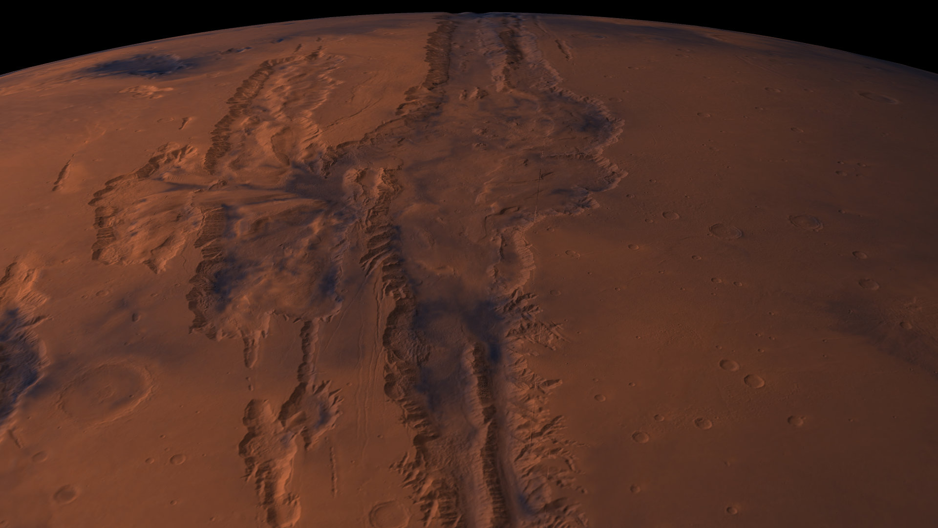
Figure 2: Close-up of some of Mars’s “canals” in Crusta Mars, based on satellite topography and color imagery data.
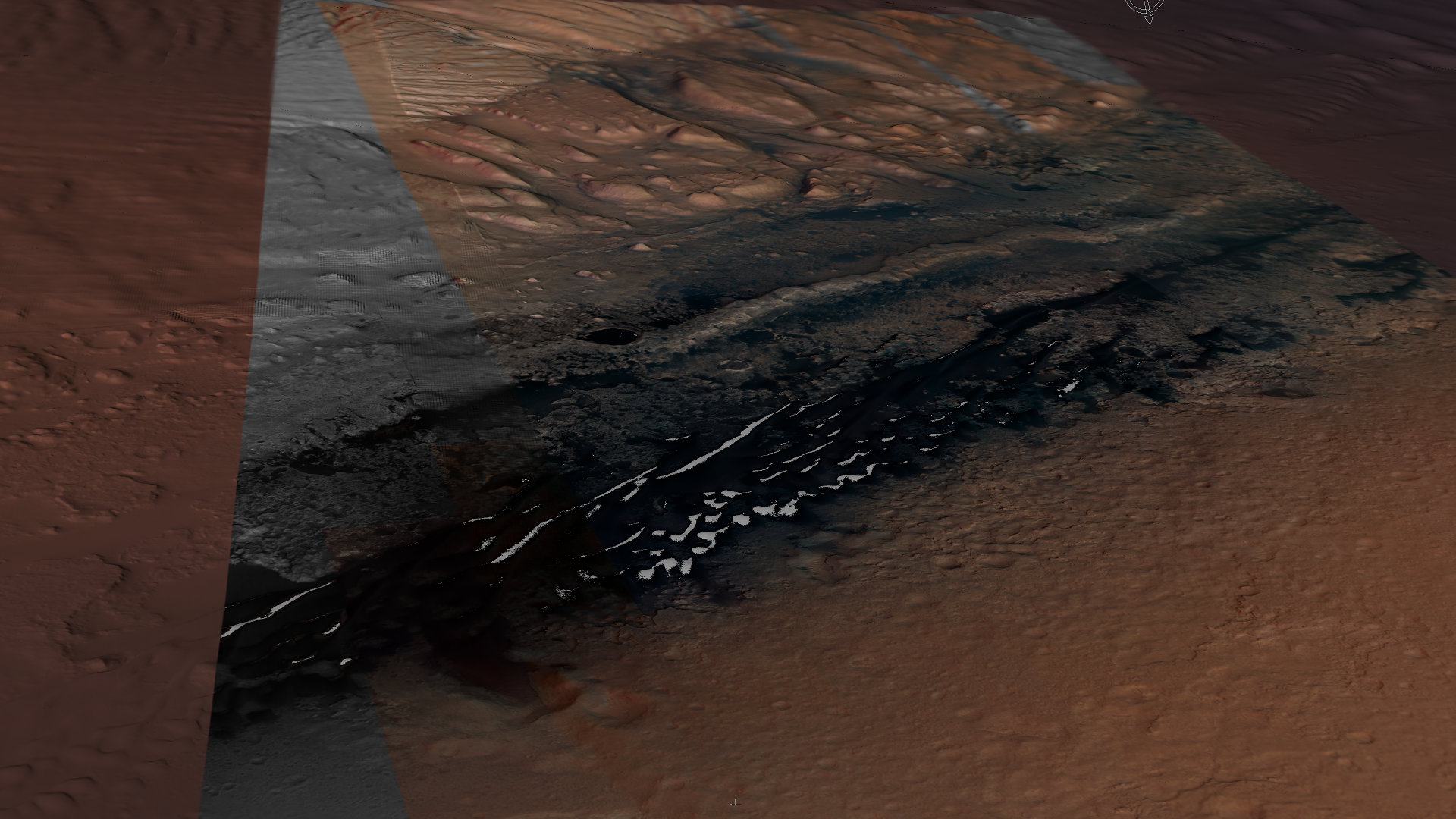
Figure 3: Close-up of Curiosity rover’s area of exploration with regional high-resolution color data, with the original landing site center bottom (indicated by white cross), looking towards Aeolis Mons (Mount Sharp).
The Crusta data sets we assembled, shown in Figures 2 and 3, ended up being 37 GB on disk, 27 GB for topography and 10 GB for color imagery.
NavCam/MastCam Data
The data sources for our second 3D model were some of the rover’s sensors themselves, specifically its navigation camera (“NavCam”), which is a black&white stereo camera used for 3D environment reconstruction, and its mast camera (“MastCam”), which is a color camera.
I combined several individual 3D point clouds that were reconstructed from NavCam stereo pairs into a single 3D point cloud using our LiDAR Viewer software, removed points representing the rover themselves (I called those “rover selfies”), and then converted the combined point cloud into a gridded elevation model with 5cm grid spacing.
In a second step, I textured that elevation model by projecting several dozen MastCam pictures onto it, which involved writing a reader for a custom NASA image file format, deriving projection/unprojection formulas for a custom NASA photogrammetric camera parameter representation, and finally creating a utility to merge all those projected images into a unified texture map (’twas a long day).
I then inserted a 3D CAD model of the rover, which we had received from JPL all those years ago, into the reconstructed and texture-mapped terrain by lining it up with the “rover selfie” points I had removed earlier, meaning that the CAD model in Figures 4 and 5 is positioned exactly where the rover actually stood while capturing the source point clouds and color images, down to the centimeter and the fact that it’s atilt by a dozen degrees or so, having been driving up an incline at the time.
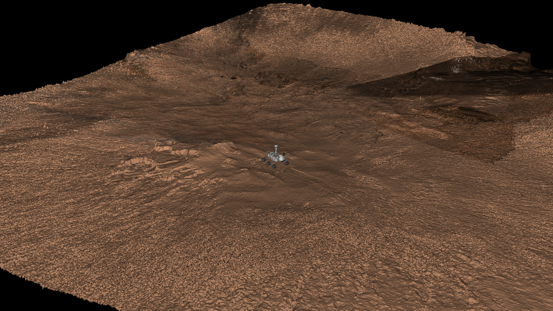
Figure 4: 3D CAD model of Curiosity rover (courtesy of JPL), positioned on terrain reconstructed from NavCam stereo pairs, and textured with MastCam images.
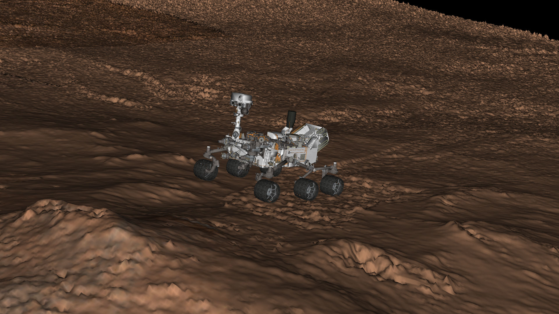
Figure 5: Close-up of 3D CAD model of Curiosity rover (courtesy of JPL), positioned on terrain reconstructed from NavCam stereo pairs, and textured with MastCam images.
“Mixed Reality”
We’ll have to wait until the special airs to find out what they really filmed, and what didn’t end up on the cutting room floor, but I shot some ad-hoc footage on my mobile phone during preparation that shows what someone interacting with virtual data in front of a projection screen should look like (only with better video and audio quality, one would hope):
Figure 6: Dawn explaining some of the rover’s instruments and features, using a “mixed reality” setup consisting of a Vive VR headset and a front-projected screen, filmed with a mobile phone with a Vive tracker attached.
Screen Calibration
In the video above, pay close attention to the Vive controller Dawn is using to point out features of interest. It has two “shadows:” first, the actual shadow from the projector, which, due to the projector’s very short throw distance, is mostly out of the way; and second, the controller’s graphical representation in the virtual world. What made me proud is that the latter “shadow” lines up very well with the real controller, to the point where it is mostly invisible, unless the controller is very close to the camera or moving quickly.
I achieved this by carefully measuring the projected image’s size, position, and orientation in the 3D coordinate system defined by the Vive’s Lighthouse tracking system prior to filming. I displayed a grid of vertical and horizontal lines, 200 pixels apart, and measured the 3D positions of the resulting 7×4 line intersections (ModLab’s projector only as 1280×720 pixels) using one of the Vive controllers.
I also created an “ideal” version of the same point positions in the image’s desired coordinate system, meaning inside the x,y plane, with the x axis corresponding to pixel rows and the y axis corresponding to pixel columns. For example, in that “ideal” coordinate system, the position of the lower-left line intersection was (0.055555, 0.083333, 0.0). Importantly, I never measured the actual corners or edges of the projected image; all measured points were well within the image.
I then fed the two point sets into one of Vrui’s calibration utilities, which calculated the optimal alignment transformation from the image’s own coordinate system to the Vive’s coordinate system (see Figure 7). This resulted in the position of the image’s lower-left corner in 3D space (which, again, I never measured directly), the image’s horizontal and vertical axes, and the image’s total width and height (which I also never measured directly). Taken together, those are the calibration parameters needed to render a correctly-aligned “mixed reality” view.
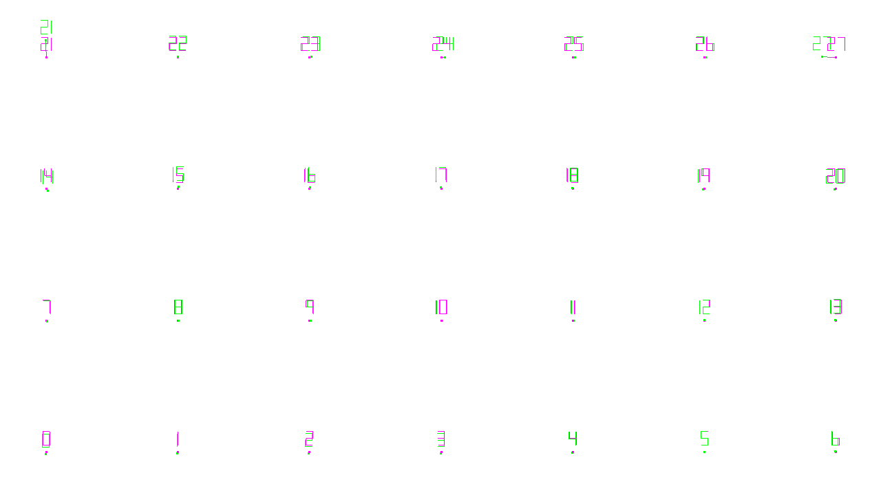
Figure 7: Screen calibration by aligning an idealized set of 3D grid point positions with a set of measured 3D positions of those same points. Purple points are ideal, green points are measured. Overall alignment residual was 2.7mm RMS.
Looking more closely at Figure 7, one can see that the bottom three rows of points line up very well, but there are discrepancies in the top row. That is because the top row of grid points was close to the boundary of the space covered by the Lighthouse base stations, and therefore had reduced tracking quality. Fortunately, the alignment utility rejected some of those points as outliers (most importantly, numbers 21 and 27), and delivered a very good result with an overall alignment error of less than 3mm RMS, which explains the video clip in Figure 6.
This is one of the primary reasons for using this somewhat involved calibration procedure: had I only measured the image’s four corners, the relatively poor tracking on the upper edge would have caused about 3cm of misalignment across the image. The other benefit of this method is that it can also correct for keystone distortion, but that wasn’t an issue here. The two main causes of remaining misalignment in the clip in Figure 6 were, first, that I was holding the Vive tracker to my phone with my hand, which wasn’t particularly precise and caused the misalignment when the controller was close to the camera; and second, the projector’s internal frame delay, which caused the misalignment under fast controller movement.
From Screen To Film
What worries me a little is how much of my careful preparation will actually end up in the show. When working with a professional film crew, one has to be mindful that those guys are actual professionals, meaning they won’t just let some random computer scientist tell them how to do their jobs. I had learned that lesson before, and was determined not to make the same mistakes again this time. I explained during our early video conferences why I was going to track their camera, why it was important for me to have the displayed imagery line up correctly with the real user, showed them video clips comparing tracked and non-tracked cameras, etc., and while the crew were again on board with that, at least in principle, their instincts took over at several points during the day, and they ruined some takes (at least as far as I am concerned) by moving the camera without letting me re-measure its position, while it was outside the Lighthouse system’s tracking range so automatic tracking didn’t work.
While that in itself is not a problem — they shot enough footage for three specials — I’m concerned that they might pick the “bad” takes over the “good” ones during editing because they might deem the former more visually interesting. While agree that a video clip of a public speaker with an unzipped fly may be more “interesting” than a normal clip, I, as that public speaker, would still not like that clip being used over an alternative take where I was properly attired. Unfortunately, that was the point where the director and I did not exactly see eye-to-eye. I tried to liken a misaligned projection to having a boom mike in the frame, but they didn’t go for that analogy. We’ll see how it turns out.
Local Collaboration
Our second idea for this video shoot was to use Vrui’s brand new, and still under development, collaboration infrastructure to have two people in the same physical space and the same virtual world at the same time, using ModLab’s second Vive headset, with Dawn explaining Mars exploration to an Earth & Planetary Sciences undergraduate student as a stand-in for the TV audience. Alas, the film crew’s director nixed that idea on the spot, although we agreed on it earlier. Not only did that undergrad waste most of her Saturday; I also wasted a good chunk of the preceding week trying to get the collaboration software ready for prime time. Too bad.
