How Does VR Create the Illusion of Reality?

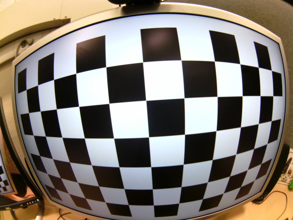
I’ve recently written a loose series of articles trying to explain certain technical aspects of virtual reality, such as what the lenses in VR headsets do, or why there is some blurriness, but I haven’t — or at least haven’t in a few years — tackled the big question:

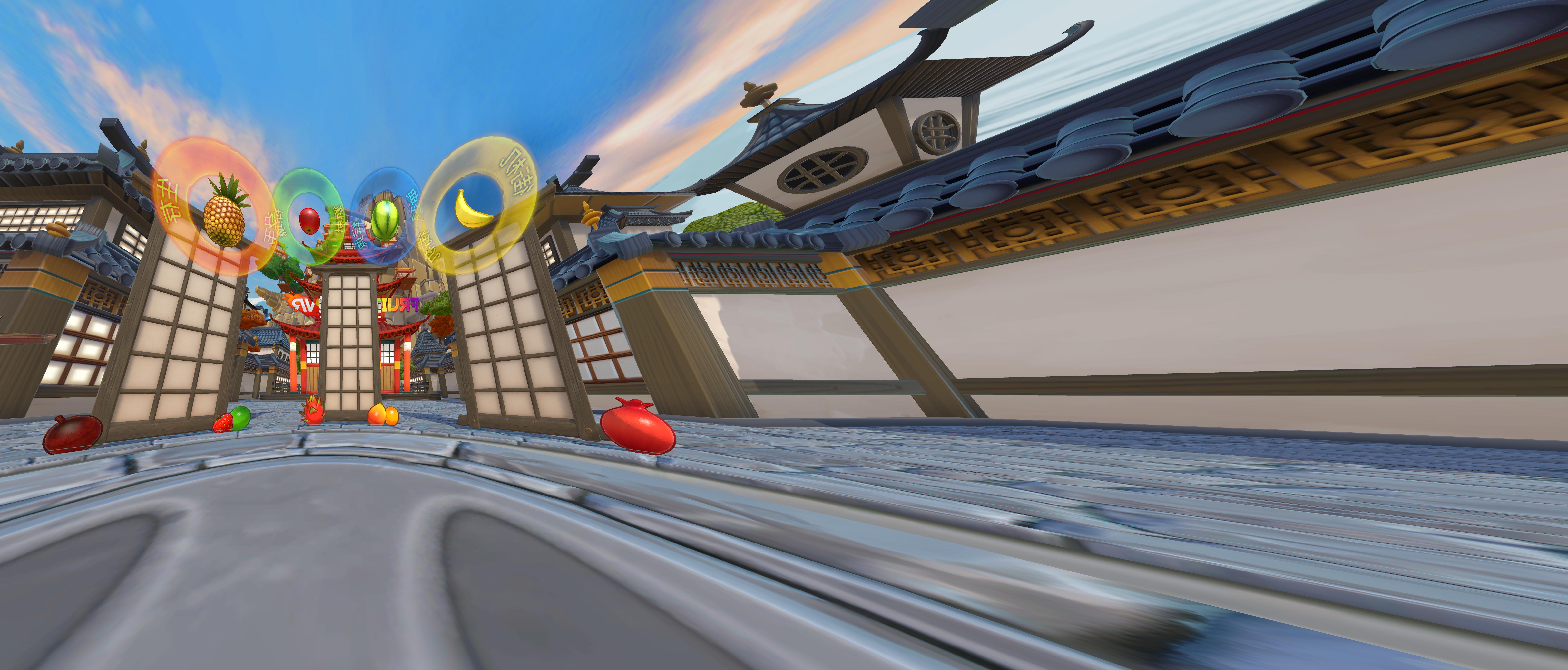
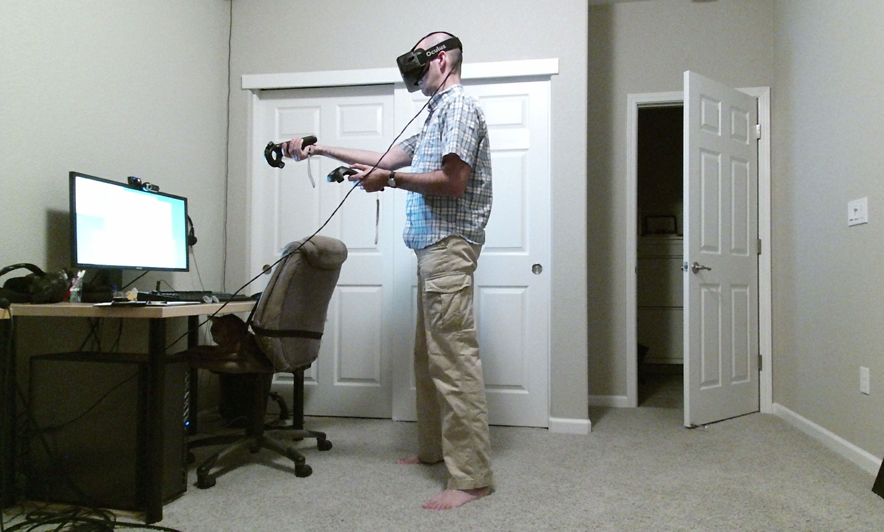
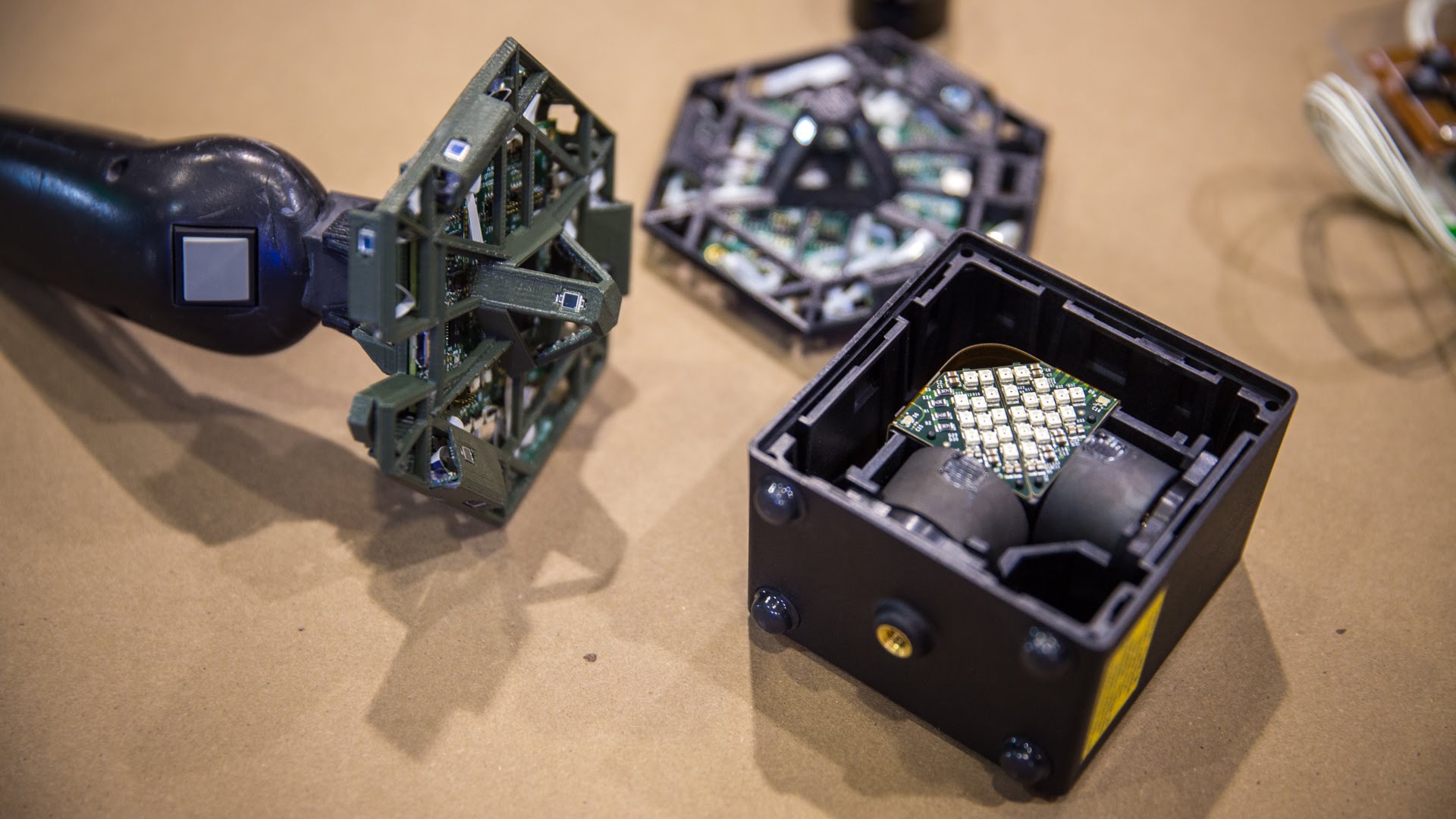
How do all the technical components of VR headsets, e.g., screens, lenses, tracking, etc., actually come together to create realistic-looking virtual environments? Specifically, why do virtual environment in VR look more “real” compared to when viewed via other media, for example panoramic video?

The reason I’m bringing this up again is that the question keeps getting asked, and that it’s really kinda hard to answer. Most attempts to answer it fall back on technical aspects, such as stereoscopy, head tracking, etc., but I find that this approach somewhat misses the point by focusing on individual components, or at least gets mired in technical details that don’t make much sense to those who have to ask the question in the first place.

I prefer to approach the question from the opposite end: not through what VR hardware produces, but instead through how the viewer perceives 3D objects and/or environments, and how either the real world on the one hand, or virtual reality displays on the other, create the appropriate visual input to support that perception.

The downside with that approach is that it doesn’t lend itself to short answers. In fact, last summer, I gave a 25 minute talk about this exact topic at the 2016 VRLA Summer Expo. It may not be news, but I haven’t linked this video from here before, and it’s probably still timely:

Continue reading

Projection and Distortion in Wide-FoV HMDs

There is an on-going, but already highly successful, Kickstarter campaign for a new VR head-mounted display with a wide (200°) field of view (FoV): Pimax 8k. As I have not personally tried this headset — only its little brother, Pimax 4k, at the 2017 SVVR Expo — I cannot discuss and evaluate all the campaign’s promises. Instead, I want to focus on one particular issue that’s causing a bit of confusion and controversy at the moment.

Early reviewers of Pimax 8k prototypes noticed geometric distortion, such as virtual objects not appearing in the correct places and shifting under head movement, and the campaign responded by claiming that these distortions “could be fixed by improved software or algorithms” (paraphrased). The ensuing speculation about the causes of, and potential fixes for, this distortion has mostly been based on wrong assumptions and misunderstandings of how geometric projection for wide-FoV VR headsets is supposed to work. Adding fuel to the fire, the campaign released a frame showing “what is actually rendered to the screen” (see Figure 1), causing further confusion. The problem is that the frame looks obviously distorted, but that this obvious distortion is not what the reviewers were complaining about. On the contrary, this is what a frame rendered to a high-FoV VR headset should look like. At least, if one ignores lenses and lens distortion, which is what I will continue to do for now.

Figure 1: Frame as rendered to one of the Pimax 8k’s screens, according to the Kickstarter campaign. (Probably not 100% true, as this appears to be a frame submitted to SteamVR’s compositor, which subsequently applies lens distortion correction.)

Continue reading

Measuring the Effective Resolution of Head-mounted Displays

Why does everything in my VR headset look so pixelated? It’s supposed to be using a 2160×1200 screen, but my 1080p desktop monitor looks so much sharper!

This is yet another fundamental question about VR that pops up over and over again, and like the others I have addressed previously, it leads to interesting deeper observations. So, why do current-generation head-mounted displays appear so low-resolution?

Here’s the short answer: In VR headsets, the screen is blown up to cover a much larger area of the user’s field of vision than in desktop settings. What counts is not the total number of pixels, and especially not the display’s resolution in pixels per inch, but the resolution of the projected virtual image in pixels per degree, as measured from the viewer’s eyes. A 20″ desktop screen, when viewed from a typical distance of 30″, covers 37° of the viewer’s field of vision, diagonally. The screen (or screens) inside a modern VR headset cover a much larger area. For example, I measured the per-eye field of view of the HTC Vive as around 110°x113° under ideal conditions, or around 130° diagonally (it’s complicated), or three and a half times as much as that of the 20″ desktop monitor. Because a smaller number of pixels (1080×1200 per eye) is spread out over a much larger area, each pixel appears much bigger to the viewer.

Now for the long answer.

Continue reading

A HoloArticle

Here is an update on my quest to stay on top of all things “holo:” HoloLamp and RealView “Live Holography.” While the two have really nothing to do with each other, both claim the “holo” label with varying degrees of legitimacy, and happened to pop up recently.

HoloLamp

At its core, HoloLamp is a projection mapping system somewhat similar to the AR Sandbox, i.e., a combination of a set of cameras scanning a projection surface and a viewer’s face, and a projector drawing a perspective-correct image, from the viewer’s point of view, onto said projection surface. The point of HoloLamp is to project images of virtual 3D objects onto arbitrary surfaces, to achieve effects like the Millenium Falcon’s holographic chess board in Star Wars: A New Hope. Let’s see how it works, and how it falls short of this goal.

Creating convincing virtual three-dimensional objects via projection is a core technology of virtual reality, specifically the technology that is driving CAVEs and other screen-based VR displays. To create this illusion, a display system needs to know two things: the exact position of the projection surface in 3D space, and the position of the viewer’s eyes in the same 3D space. Together, these two provide just the information needed to set up the correct perspective projection. In CAVEs et al., the position of the screen(s) is fixed and precisely measured during installation, and the viewer’s eye positions are provided via real-time head tracking.

As one goal of HoloLamp is portability, it cannot rely on pre-installation and manual calibration. Instead, HoloLamp scans and creates a 3D model of the projection surface when turned on (or asked to do so, I guess). It does this by projecting a sequence of patterns, and observing the perspective distortion of those patterns with a camera looking in the projection direction. This is a solid and well-known technology called structured-light 3D scanning, and can be seen in action at the beginning of this HoloLamp video clip. To extract eye positions, HoloLamp uses an additional set of cameras looking upwards to identify and track the viewer’s face, probably using off-the-shelf face tracking algorithms such as the Viola-Jones filter. Based on that, the software can project 3D objects using one or more projection matrices, depending on whether the projection surface is planar or not. The result looks very convincing when shot through a regular video camera:

Continue reading

Vrui on Oculus Rift DK2

I know, the Oculus Rift DK2 is obsolete equipment, but nonetheless — there are a lot of them still out there, it’s still a decent VR headset for seated applications, I guess they’re getting cheaper on eBay now, and I put in all the work back then to support it in Vrui, so I might as well describe how to use it. If nothing else, the DK2 is a good way to watch DVD movies, or panoramic mono- or stereoscopic videos, in VR.

Figure 1: Using an Oculus Rift DK2 headset with a pair of Vive controllers -- because why not?

Figure 1: Using an Oculus Rift DK2 headset with a pair of Vive controllers — because why not?

Continue reading

Remote Collaborative Immersive Visualization

I spent the last couple of days at the first annual meeting of “The Higher Education Campus Alliance for Advanced Visualization” (THE CAAV), where folks managing or affiliated with advanced visualization centers such as KeckCAVES came together to share their experiences. During the talks, I saw slides showing Vrui‘s Collaboration Infrastructure pop up here and there, and generally remote collaboration was a big topic of discussion. During breaks, I showed several people the following video on my smartphone (yes, I finally joined the 21st century), and afterwards realized that I had never written a post about this work, as most of it predates this blog. So here we go.

Continue reading

Lighthouse tracking examined

To my surprise and delight, I recently found out that Valve has been releasing Linux versions of most of their SteamVR/OpenVR run-time/SDK for a while now (OpenVR just hit version 1.0.0, go get it while it’s fresh). This is great news: it will allow me to port Vrui and all Vrui applications to the Vive headset and its tracked controllers in one fell swoop.

But before diving into developing a Lighthouse tracking driver plug-in for Vrui’s input device abstraction layer, I decided to cobble together a small testing utility to get a feel for OpenVR’s internal driver interface, and for the Lighthouse tracking system’s overall tracking quality.

Figure 1: The Lighthouse 6-DOF tracking system, disassembled.

Figure 1: The Lighthouse 6-DOF tracking system, disassembled (source).

Continue reading

Optical Properties of Current VR HMDs

With the first commercial version of the Oculus Rift (Rift CV1) now trickling out of warehouses, and Rift DK2, HTC Vive DK1, and Vive Pre already being in developers’ hands, it’s time for a more detailed comparison between these head-mounted displays (HMDs). In this article, I will look at these HMDs’ lenses and optics in the most objective way I can, using a calibrated fish-eye camera (see Figures 1, 2, and 3).

Figure 1: Picture from a fisheye camera, showing a checkerboard calibration target displayed on a 30" LCD monitor.

Figure 1: Picture from a fisheye camera, showing a checkerboard calibration target displayed on a 30″ LCD monitor.

Figure 2: Same picture as Figure 1, after rectification. The purple lines were drawn into the picture by hand to show the picture's linearity after rectification.

Figure 2: Same picture as Figure 1, after rectification. The purple lines were drawn into the picture by hand to show the picture’s linearity after rectification.

Figure 3: Rectified picture from Figure 2, re-projected into stereographic projection to simplify measuring angles.

Figure 3: Rectified picture from Figure 2, re-projected into stereographic projection to simplify measuring angles. Concentric purple circles indicate 5-degree increments away from the projection center point.

Continue reading

Oculus Rift DK2’s tracking update rate

I’ve been involved in some arguments about the inner workings of the Oculus Rift’s and HTC/Valve Vive’s tracking systems recently, and while I don’t want to get into any of that right now, I just did a little experiment.

The tracking update rate of the Oculus Rift DK2, meaning the rate at which Oculus’ tracking driver sends different position/orientation estimates to VR applications, is 1000 Hz. However, the time between updates is 2ms, meaning that the driver updates the position/orientation, and then updates it again immediately afterwards, 500 times per second.

This is not surprising at all, given my earlier observation that the DK2 samples its internal IMU at a rate of 1000 Hz, and sends data packets containing 2 IMU samples each to the host at a rate of 500 Hz. The tracking driver is then kind enough to process these samples individually, and pass updated tracking data to applications after it’s done processing each one. That second part is maybe a bit superfluous, but I’ll take it.

Here is a (very short excerpt of a) dump from the test application I wrote:

0.00199484: -0.0697729, -0.109664, -0.458555
6.645e-06 : -0.0698003, -0.110708, -0.458532
0.00199313: -0.069828 , -0.111758, -0.45851
6.012e-06 : -0.0698561, -0.112813, -0.458488
0.00200075: -0.0698847, -0.113875, -0.458466
6.649e-06 : -0.0699138, -0.114943, -0.458445
0.0019885 : -0.0699434, -0.116022, -0.458427
5.915e-06 : -0.0699734, -0.117106, -0.45841
0.0020142 : -0.070004 , -0.118196, -0.458393
5.791e-06 : -0.0700351, -0.119291, -0.458377
0.00199589: -0.0700668, -0.120392, -0.458361
6.719e-06 : -0.070099 , -0.121499, -0.458345
0.00197487: -0.0701317, -0.12261 , -0.45833
6.13e-06  : -0.0701651, -0.123727, -0.458314
0.00301248: -0.0701991, -0.124849, -0.458299
5.956e-06 : -0.0702338, -0.125975, -0.458284
0.00099399: -0.0702693, -0.127107, -0.458269
5.971e-06 : -0.0703054, -0.128243, -0.458253
0.0019938 : -0.0703423, -0.129384, -0.458238
5.938e-06 : -0.0703799, -0.130529, -0.458223
0.00200243: -0.0704184, -0.131679, -0.458207
7.434e-06 : -0.0704576, -0.132833, -0.458191
0.0019831 : -0.0704966, -0.133994, -0.458179
5.957e-06 : -0.0705364, -0.135159, -0.458166
0.00199577: -0.0705771, -0.136328, -0.458154
5.974e-06 : -0.0706185, -0.137501, -0.458141

The first column is the time interval between each row and the previous row, in seconds. The second to fourth rows are the reported (x, y, z) position of the headset.

I hope this puts the myth to rest that the DK2 only updates its tracking data when it receives a new frame from the tracking camera, which is 60 times per second, and confirms that the DK2’s tracking is based on dead reckoning with drift correction. Now, while it is possible that the commercial version of the Rift does things differently, I don’t see a reason why it should.

PS: If you look closely, you’ll notice an outlier in rows 15 and 17: the first interval is 3ms, and the second interval is only 1ms. One sample missed the 1000 Hz sample clock, and was delivered on the next update.

Lasers Are Not Magic

“Can I make a full-field-of-view AR or VR display by directly shining lasers into my eyes?”

No.

Well, technically, you can, but not in the way you probably imagine if you asked that question. What you can’t do is mount some tiny laser emitter somewhere out of view, have it shine a laser directly into your pupil, and expect to get a virtual image covering your entire field of view (see Figure 1). Light, and your eyes, don’t work that way.

Figure 1: A magical retinal display using a tiny laser emitter somewhere off to the side of each eye. This doesn't work in reality.

Figure 1: A magical retinal display using a tiny laser emitter somewhere off to the side of each eye. This doesn’t work in reality. If a single beam of light entering the eye could be split up to illuminate large parts of the retina, real-world vision would not work.

Continue reading