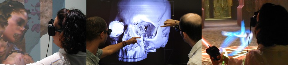
I just moved all my Kinects back to my lab after my foray into experimental mixed-reality theater a week ago, and just rebuilt my 3D video capture space / tele-presence site consisting of an Oculus Rift head-mounted display and three Kinects. Now that I have a new extrinsic calibration procedure to align multiple Kinects to each other (more on that soon), and managed to finally get a really nice alignment, I figured it was time to record a short video showing what multi-camera 3D video looks like using current-generation technology (no, I don’t have any Kinects Mark II yet). See Figure 1 for a still from the video, and the whole thing after the jump.
Figure 1: A still frame from the video, showing the user’s real-time “holographic” avatar from the outside, providing a literal kind of out-of-body experience to the user.
A little more than a month ago, I wrote a pair of articles investigating and explaining the internals of the Rift’s display, and how small deviations in calibration have a large effect on the perceived size of the virtual world, and the degree of “solidity” (for lack of a better word) of the virtual objects therein. In those posts, I pointed out that a single lens distortion correction formula doesn’t suffice, because lens distortion parameters depend on the position of the viewers’ eyes relative to the lenses, particularly the eye/lens distance, otherwise known as “eye relief.” And guess what: I just got an email via the Oculus developer mailing list announcing the (preview) release of SDK version 0.3.1, which lists eye relief-dependent lens correction as one of its major features.
Maybe I should keep writing articles on the virtues of 3D pupil tracking, and the obvious benefits of adding an inertially/optically tracked 6-DOF input device to the consumer-level Rift’s basic package, and those things will happen as well. 🙂
Update: There have been complaints that the post below is an overly complicated and confusing explanation of the IPD measurement process. Maybe that’s so. Therefore, here’s the TL;DR version of how the process works. If you want to know why it works, read on below.
Stand in front of a mirror and hold a ruler up to your nose, such that the measuring edge runs directly underneath both your pupils.
Close your right eye and look directly at your left eye. Move the ruler such that the “0” mark appears directly underneath the center of your left pupil. Try to keep the ruler still for the next step.
Close your left eye and look directly at your right eye. The mark directly underneath the center of your right pupil is your inter-pupillary distance.
Here follows the long version:
I’ve recentlytalked about the importance of calibrating 3D displays, especially head-mounted displays, which have very tight tolerances. An important part of calibration is entering each user’s personal inter-pupillary distance. Even when using the eyeball center as projection focus point (as I describe in the second post linked above), the distance between the eyeballs’ centers is the same as the inter-pupillary distance.
So how do you actually go about determining your IPD? You could go to an optometrist, of course, but it turns out it’s very easy to do it accurately at home. As it so happened, I did go to an optometrist recently (for my annual check-up), and I asked him to measure my IPD as well while he was at it. I was expecting him to pull out some high-end gizmo, but instead he pulled up a ruler. So that got me thinking.
Figure 1: How to precisely measure infinity-converged inter-pupillary distance using only a mirror and a ruler. Focus on the left eye in step one and mark point A; focus on the right eye in step two and mark point B; the distance between points A and B is precisely the infinity-converged inter-pupillary distance (and also the eyeball center distance).
Now this is why I run a blog. In my video and post on the Oculus Rift’s internals, I talked about distortions in 3D perception when the programmed-in camera positions for the left and right stereo views don’t match the current left and right pupil positions, and how a “perfect” HMD would therefore need a built-in eye tracker. That’s still correct, but it turns out that I could have done a much better job approximating proper 3D rendering when there is no eye tracking.
This improvement was pointed out by a commenter on the previous post. TiagoTiago asked if it wouldn’t be better if the virtual camera were located at the centers of the viewer’s eyeballs instead of at the pupils, because then light rays entering the eye straight on would be represented correctly, independently of eye vergence angle. Spoiler alert: he was right. But I was skeptical at first, because, after all, that’s just plain wrong. All light rays entering the eye converge at the pupil, and therefore that’s the only correct position for the virtual camera.
Well, that’s true, but if the current pupil position is unknown due to lack of eye tracking, then the only correct thing turns into just another approximation, and who’s to say which approximation is better. My hunch was that the distortion effects from having the camera in the center of the eyeballs would be worse, but given that projection in an HMD involving a lens is counter-intuitive, I still had to test it. Fortunately, adding an interactive foveating mechanism to my lens simulation application was simple.
Turns out that I was wrong, and that in the presence of a collimating lens, i.e., a lens that is positioned such that the HMD display screen is in the lens’ focal plane, distortion from placing the camera in the center of the eyeball is significantly less pronounced than in my approach. Just don’t ask me to explain it for now — it’s due to the “special properties of the collimated light.” 🙂
I’ve just returned from the 2013 Augmented World Expo, where we showcased our Augmented Reality Sandbox. This marked the first time we took the sandbox on the road; we had only shown it publicly twice before, during UC Davis‘ annual open house in 2012 and 2013. The first obstacle popped up right from the get-go: the sandbox didn’t fit through the building doors! We had to remove the front door’s center column to get the sandbox out and into the van. And we needed a forklift to get it out of the van at the expo, but fortunately there were pros around.
Figure 1: Me, digging into the sandbox, with a few onlookers. Photo provided by Marshall Millett.
My friend Serban got his Oculus Rift dev kit in the mail today, and he called me over to check it out. I will hold back a thorough evaluation until I get the Rift supported natively in my own VR software, so that I can run a direct head-to-head comparison with my other HMDs, and also my screen-based holographic display systems (the head-tracked 3D TVs, and of course the CAVE), using the same applications. Specifically, I will use the Quake ||| Arena viewer to test the level of “presence” provided by the Rift; as I mentioned in my previous post, there are some very specific physiological effects brought out by that old chestnut, and my other HMDs are severely lacking in that department, and I hope that the Rift will push it close to the level of the CAVE. But here are some early impressions.
Figure 1: What it would look like to unbox an Oculus VR dev kit, if one were to have such a thing.
“Virtual Worlds Using Head-mounted Displays” is the most complex video I’ve made so far, and I figured I should explain how it was done (maybe as a response to people who might say I “cheated”).
The original stereo projection system, driven by a 2006 Mac Pro, was getting long in the tooth, and in the process of upgrading to higher-resolution and brighter projectors, we finally convinced the powers-that-be to get a top-of-the line Linux PC instead of yet another Mac (for significant savings, one might add). While the Ubuntu OS and Vrui application set had already been pre-installed by KeckCAVES staff in the home office, I still had to go up to the lake to configure the operating system and Vrui to render to the new projectors, update all Vrui software, align the projectors, and train the local docents in using Linux and the new Vrui application versions.
Boy, is my face red. I just uploaded two videos about intrinsic Kinect calibration to YouTube, and wrote two blog posts about intrinsic and extrinsic calibration, respectively, and now I find out that the factory calibration data I’ve always suspected was stored in the Kinect’s non-volatile RAM has actually been reverse-engineered. With the official Microsoft SDK out that should definitely not have been a surprise. Oh, well, my excuse is I’ve been focusing on other things lately.
So, how good is it? A bit too early to tell, because some bits and pieces are still not understood, but here’s what I know already. As I mentioned in the post on intrinsic calibration, there are several required pieces of calibration data:
2D lens distortion correction for the color camera.
2D lens distortion correction for the virtual depth camera.
Non-linear depth correction (caused by IR camera lens distortion) for the virtual depth camera.
Conversion formula from (depth-corrected) raw disparity values (what’s in the Kinect’s depth frames) to camera-space Z values.
Unprojection matrix for the virtual depth camera, to map depth pixels out into camera-aligned 3D space.
Projection matrix to map lens-corrected color pixels onto the unprojected depth image.