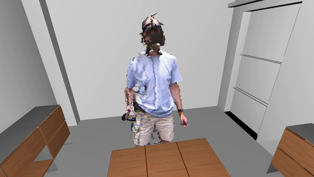
I just moved all my Kinects back to my lab after my foray into experimental mixed-reality theater a week ago, and just rebuilt my 3D video capture space / tele-presence site consisting of an Oculus Rift head-mounted display and three Kinects. Now that I have a new extrinsic calibration procedure to align multiple Kinects to each other (more on that soon), and managed to finally get a really nice alignment, I figured it was time to record a short video showing what multi-camera 3D video looks like using current-generation technology (no, I don’t have any Kinects Mark II yet). See Figure 1 for a still from the video, and the whole thing after the jump.
Tag Archives: HMD
Gaze-directed Text Entry in VR Using Quikwrite
Text entry in virtual environments is one of those old problems that never seem to get solved. The core issue, of course, is that users in VR either don’t have keyboards (because they are in a CAVE, say), or can’t effectively use the keyboard they do have (because they are wearing an HMD that obstructs their vision). To the latter point: I consider myself a decent touch typist (my main keyboard doesn’t even have key labels), but the moment I put on an HMD, that goes out the window. There’s an interesting research question right there — do typists need to see their keyboards in their peripheral vision to use them, even when they never look at them directly? — but that’s a topic for another post.
Until speech recognition becomes powerful and reliable enough to use as an exclusive method (and even then, imagining having to dictate “for(int i=0;i<numEntries&&entries[i].key!=searchKey;++i)” already gives me a headache), and until brain/computer interfaces are developed and we plug our computers directly into our heads, we’re stuck with other approaches.
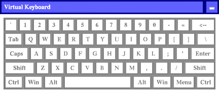
Unsurprisingly, the go-to method for developers who don’t want to write a research paper on text entry, but just need text entry in their VR applications right now, and don’t have good middleware to back them up, is a virtual 3D QWERTY keyboard controlled by a 2D or 3D input device (see Figure 1). It’s familiar, straightforward to implement, and it can even be used to enter text.
Someone at Oculus is Reading my Blog
I am getting the feeling that Big Brother is watching me. When I released the inital version of the Vrui VR toolkit with native Oculus Rift support, it had magnetic yaw drift correction, which the official Oculus SDK didn’t have at that point (Vrui doesn’t use the Oculus SDK at all to talk to the Rift; it has its own tracking driver that talks to the Rift’s inertial movement unit directly via USB, and does its own sensor fusion, and also does its own projection setup and lens distortion correction). A week or so later, Oculus released an updated SDK with magnetic drift correction.
A little more than a month ago, I wrote a pair of articles investigating and explaining the internals of the Rift’s display, and how small deviations in calibration have a large effect on the perceived size of the virtual world, and the degree of “solidity” (for lack of a better word) of the virtual objects therein. In those posts, I pointed out that a single lens distortion correction formula doesn’t suffice, because lens distortion parameters depend on the position of the viewers’ eyes relative to the lenses, particularly the eye/lens distance, otherwise known as “eye relief.” And guess what: I just got an email via the Oculus developer mailing list announcing the (preview) release of SDK version 0.3.1, which lists eye relief-dependent lens correction as one of its major features.
Maybe I should keep writing articles on the virtues of 3D pupil tracking, and the obvious benefits of adding an inertially/optically tracked 6-DOF input device to the consumer-level Rift’s basic package, and those things will happen as well. 🙂
How to Measure Your IPD
Update: There have been complaints that the post below is an overly complicated and confusing explanation of the IPD measurement process. Maybe that’s so. Therefore, here’s the TL;DR version of how the process works. If you want to know why it works, read on below.
- Stand in front of a mirror and hold a ruler up to your nose, such that the measuring edge runs directly underneath both your pupils.
- Close your right eye and look directly at your left eye. Move the ruler such that the “0” mark appears directly underneath the center of your left pupil. Try to keep the ruler still for the next step.
- Close your left eye and look directly at your right eye. The mark directly underneath the center of your right pupil is your inter-pupillary distance.
Here follows the long version:
I’ve recently talked about the importance of calibrating 3D displays, especially head-mounted displays, which have very tight tolerances. An important part of calibration is entering each user’s personal inter-pupillary distance. Even when using the eyeball center as projection focus point (as I describe in the second post linked above), the distance between the eyeballs’ centers is the same as the inter-pupillary distance.
So how do you actually go about determining your IPD? You could go to an optometrist, of course, but it turns out it’s very easy to do it accurately at home. As it so happened, I did go to an optometrist recently (for my annual check-up), and I asked him to measure my IPD as well while he was at it. I was expecting him to pull out some high-end gizmo, but instead he pulled up a ruler. So that got me thinking.
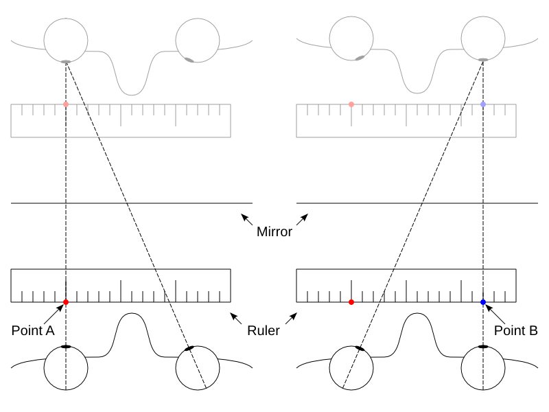
Figure 1: How to precisely measure infinity-converged inter-pupillary distance using only a mirror and a ruler. Focus on the left eye in step one and mark point A; focus on the right eye in step two and mark point B; the distance between points A and B is precisely the infinity-converged inter-pupillary distance (and also the eyeball center distance).
Fighting Motion Sickness due to Explicit Viewpoint Rotation
Here is an interesting innovation: the developers at Cloudhead Games, who are working on The Gallery: Six Elements, a game/experience created for HMDs from the ground up, encountered motion sickness problems due to explicit viewpoint rotation when using analog sticks on game controllers, and came up with a creative approach to mitigate it: instead of rotating the view smoothly, as conventional wisdom would suggest, they rotate the view discretely, in relatively large increments (around 30°). And apparently, it works. What do you know. In their explanation, they refer to the way dancers keep themselves from getting dizzy during pirouettes by fixing their head in one direction while their bodies spin, and then rapidly whipping their heads around back to the original direction. But watch them explain and demonstrate it themselves. Funny thing is, I knew that thing about ice dancers, but never thought to apply it to viewpoint rotation in VR.
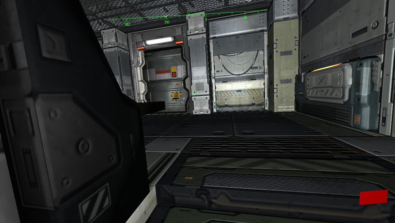
Figure 1: A still from the video showing the initial implementation of “VR Comfort Mode” in Vrui.
This is very timely, because I have recently been involved in an ongoing discussion about input devices for VR, and how they should be handled by software, and how there should not be a hardware standard but a middleware standard, and yadda yadda yadda. So I have been talking up Vrui‘s input model quite a bit, and now is the time to put up or shut up, and show how it can handle some new idea like this.
More on Desktop Embedding via VNC
I started regretting uploading my “Embedding 2D Desktops into VR” video, and the post describing it, pretty much right after I did it, because there was such an obvious thing to do, and I didn’t think of it.
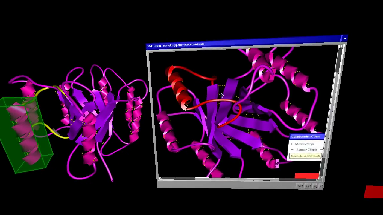
Figure 1: Screenshot from video showing VR ProtoShop run simultaneously in a 3D environment created by an Oculus Rift and a Razer Hydra, and in a 2D environment using mouse and keyboard, brought into the 3D environment via the VNC remote desktop protocol.
VR Movies
There has been a lot of discussion about VR movies in the blogosphere and forosphere (just to pick two random examples), and even on Wired, recently, with the tenor being that VR movies will be the killer application for VR. There are even downloadable prototypes and start-up companies.
But will VR movies actually ever work?
This is a tricky question, and we have to be precise. So let’s first define some terms.
When talking about “VR movies,” people are generally referring to live-action movies, i.e., the kind that is captured with physical cameras and shows real people (well, actors, anyway) and environments. But for the sake of this discussion, live-action and pre-rendered computer-generated movies are identical.
We’ll also have to define what we mean by “work.” There are several things that people might expect from “VR movies,” but not everybody might expect the same things. The first big component, probably expected by all, is panoramic view, meaning that a VR movie does not only show a small section of the viewer’s field of view, but the entire sphere surrounding the viewer — primarily so that viewers wearing a head-mounted display can freely look around. Most people refer to this as “360° movies,” but since we’re all thinking 3D now instead of 2D, let’s use the proper 3D term and call them “4π sr movies” (sr: steradian), or “full solid angle movies” if that’s easier.
The second component, at least as important, is “3D,” which is of course a very fuzzy term itself. What “normal” people mean by 3D is that there is some depth to the movie, in other words, that different objects in the movie appear at different distances from the viewer, just like in reality. And here is where expectations will vary widely. Today’s “3D” movies (let’s call them “stereo movies” to be precise) treat depth as an independent dimension from width and height, due to the realities of stereo filming and projection. To present filmed objects at true depth and with undistorted proportions, every single viewer would have to have the same interpupillary distance, all movie screens would have to be the exact same size, and all viewers would have to sit in the same position relative the the screen. This previous post and video talks in great detail about what happens when that’s not the case (it is about head-mounted displays, but the principle and effects are the same). As a result, most viewers today would probably not complain about the depth in a VR movie being off and objects being distorted, but — and it’s a big but — as VR becomes mainstream, and more people experience proper VR, where objects are at 1:1 scale and undistorted, expectations will rise. Let me posit that in the long term, audiences will not accept VR movies with distorted depth.
2D Desktop Embedding via VNC
There have been several discussions on the Oculus subreddit recently about how to integrate 2D desktops or 2D applications with 3D VR environments; for example, how to check your Facebook status while playing a game in the Oculus Rift without having to take off the headset.
This is just one aspect of the larger issue of integrating 2D and 3D applications, and it reminded me that it was about time to revive the old VR VNC client that Ed Puckett, an external contractor, had developed for the CAVE a long time ago. There have been several important changes in Vrui since the VNC client was written, especially in how Vrui handles text input, which means that a completely rewritten client could use the new Vrui APIs instead of having to implement everything ad-hoc.
Here is a video showing the new VNC client in action, embedded into LiDAR Viewer and displayed in a desktop VR environment using an Oculus Rift HMD, mouse and keyboard, and a Razer Hydra 6-DOF input device:
Small Correction to Rift’s Projection Matrix
In a previous post, I looked at the Oculus Rift’s internal projection in detail, and did some analysis of how stereo rendering setup is explained in the Rift SDK’s documentation. Looking at that again, I noticed something strange.
In the other post, I simplified the Rift’s projection matrix as presented in the SDK documentation to
which, to those in the know, doesn’t look like a regular OpenGL projection matrix, such as created by glFrustum(…). More precisely, the third row of P is off. The third-column entry should be instead of
, and the fourth-column entry should be
instead of
. To clarify, I didn’t make a mistake in the derivation; the matrix’s third row is the same in the SDK documentation.
What’s the difference? It’s subtle. Changing the third row of the projection matrix doesn’t change where pixels end up on the screen (that’s the good news). It only changes the z, or depth, value assigned to those pixels. In a standard OpenGL frustum matrix, 3D points on the near plane get a depth value of 1.0, and those on the far plane get a depth value of -1.0. The 3D clipping operation that’s applied to any triangle after projection uses those depth values to cut off geometry outside the view frustum, and the viewport projection after that will map the [-1.0, 1.0] depth range to [0, 1] for z-buffer hidden surface removal.
Using a projection matrix as presented in the previous post, or in the SDK documentation, will still assign a depth value of -1.0 to points on the far plane, but a depth value of 0.0 to points on the (nominal) near plane. Meaning that the near plane distance given as parameter to the matrix is not the actual near plane distance used by clipping and z buffering, which might lead to some geometry appearing in the view that shouldn’t, and a loss of resolution in the z buffer because only half the value range is used.
I’m assuming that this is just a typo in the Oculus SDK documentation, and that the library code does the right thing (I haven’t looked).
Oh, right, so the fixed projection matrix, for those working along, is
Game Engines and Positional Head Tracking
Oculus recently presented the “Crystal Cove,” a version of the Rift head-mounted display with built-in optical tracking, which is combined with the existing inertial tracker to provide a full 6-DOF (position and orientation) tracking solution at low latency, and it is rumored that the Crystal Cove will be released as development kit mark 2 after this year’s Game Developers Conference.
This is great news. I’ve been saying for a long time that Oculus cannot afford to drop positional head tracking on developers at the last minute, because it will break several assumptions built into game engines and other VR software (but let’s talk about game engines here). I’m also happy because the Crystal Cove uses precisely the tracking technology that I predicted: active markers (LEDs) on the headset, and an external camera placed at a fixed position in the environment. I am also sad because I didn’t manage to finish my own after-market optical tracking add-on before Oculus demonstrated their new integrated technology, but that’s life.
So why does positional head tracking break existing games? Because for the first time, the virtual camera used to render a game world is no longer under sufficient control of the software. Let’s take a step back. In a standard, desktop, 3D game, the camera is entirely controlled by the software. The software sets it to some position and orientation determined by the game logic, the 3D engine renders the virtual world for that camera setup, and the result is the displayed image.

